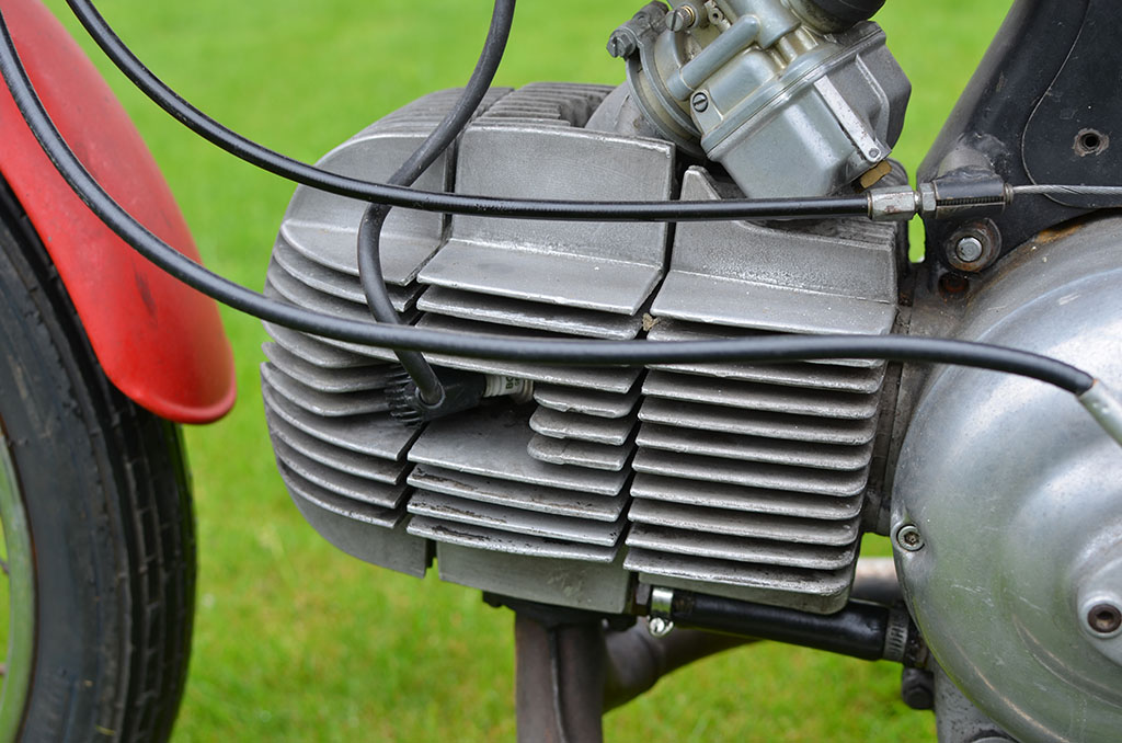
I had to change the main jet from 115 to 125 for the engine to run smooth at constant higher speeds.

I had to change the main jet from 115 to 125 for the engine to run smooth at constant higher speeds.


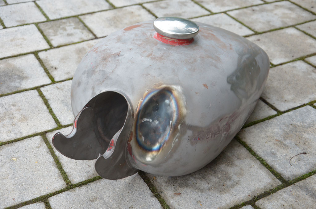
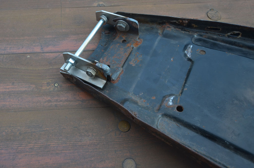
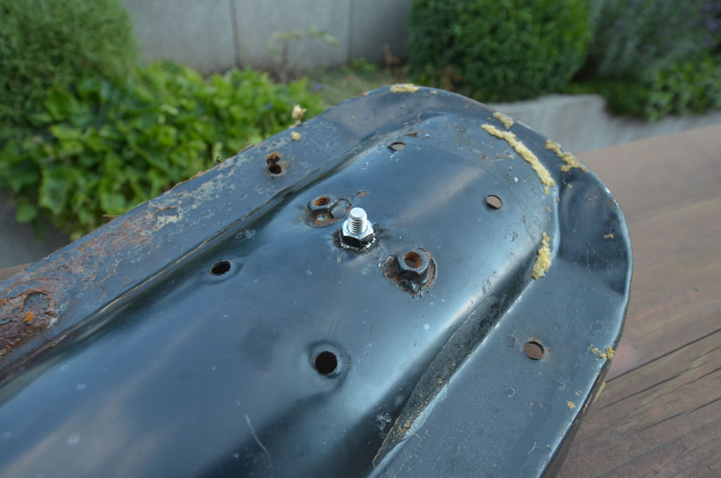
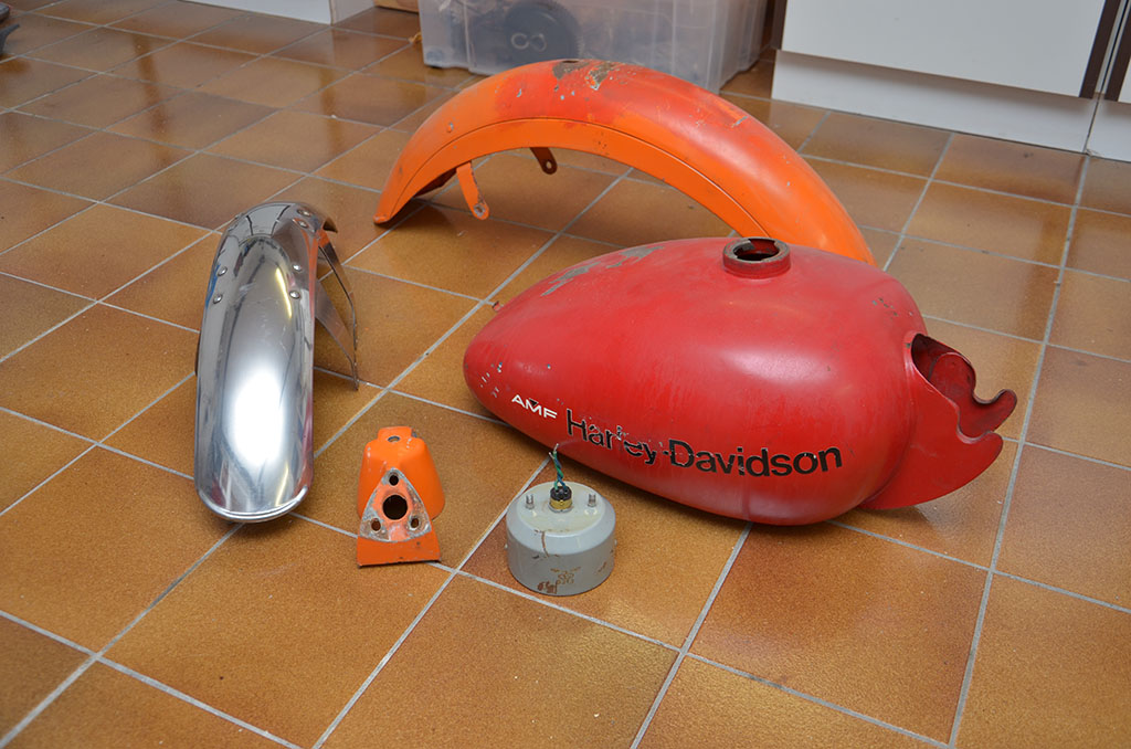
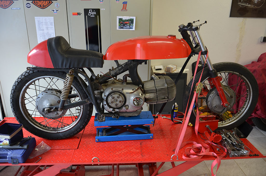
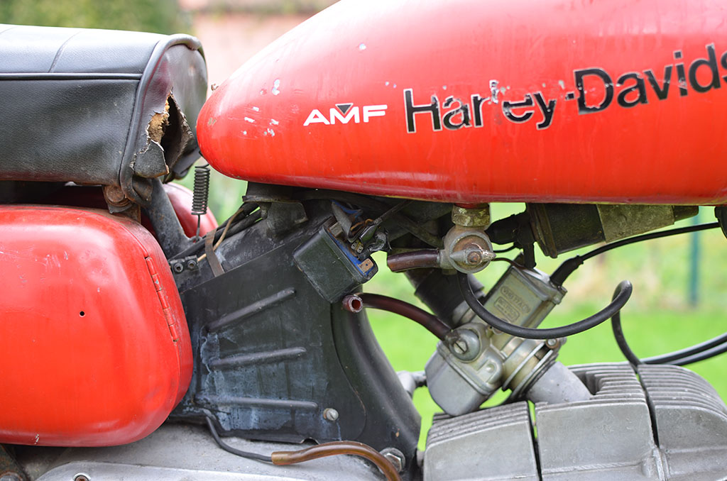
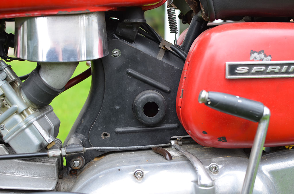
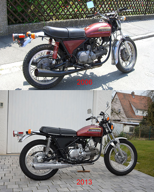
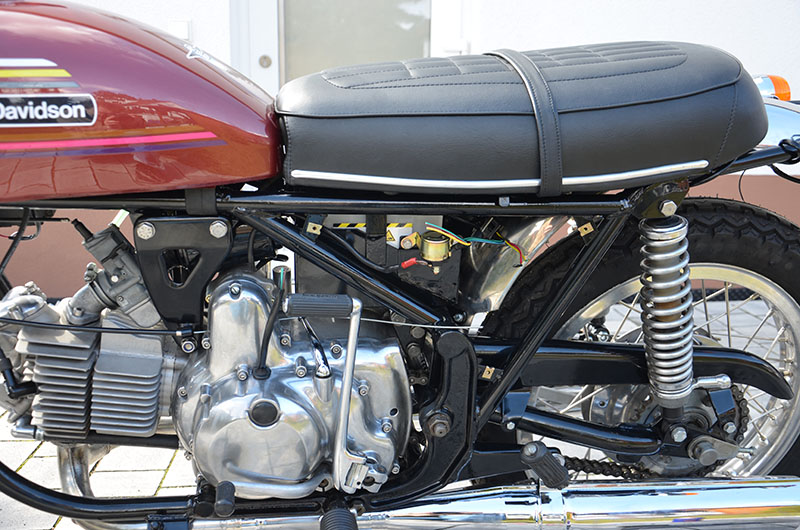
I had to modify the seat pan because the gas tank that was originally on my bike had big dents that are very hard to repair. I didn’t know about the damage, because someone filled the holes and repainted it. After removing the paint this was a big surprise. I bought a replacement gas tank on ebay. It had 1972 decals, but I was sure it is not a 1972 gas tank. When it was repainted I noticed the replacement tank is about 5 centimeters longer than my original tank!
Well, the replacement tank fits, but than there is no room for the seat. I relocated the seat 5 centimeters to the back and hopefully this will solve my problem. I will have the pan cleaned and powder coated and the seat will be recovered.

I replaced the airfilter (oval type) with a new UFI part. I also replaced the faulty LUCAS flasher relay with a modern electronic flasher relay as the turnsignals did burn constantly instant of flashing.

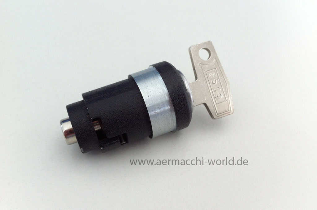
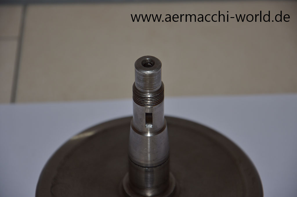
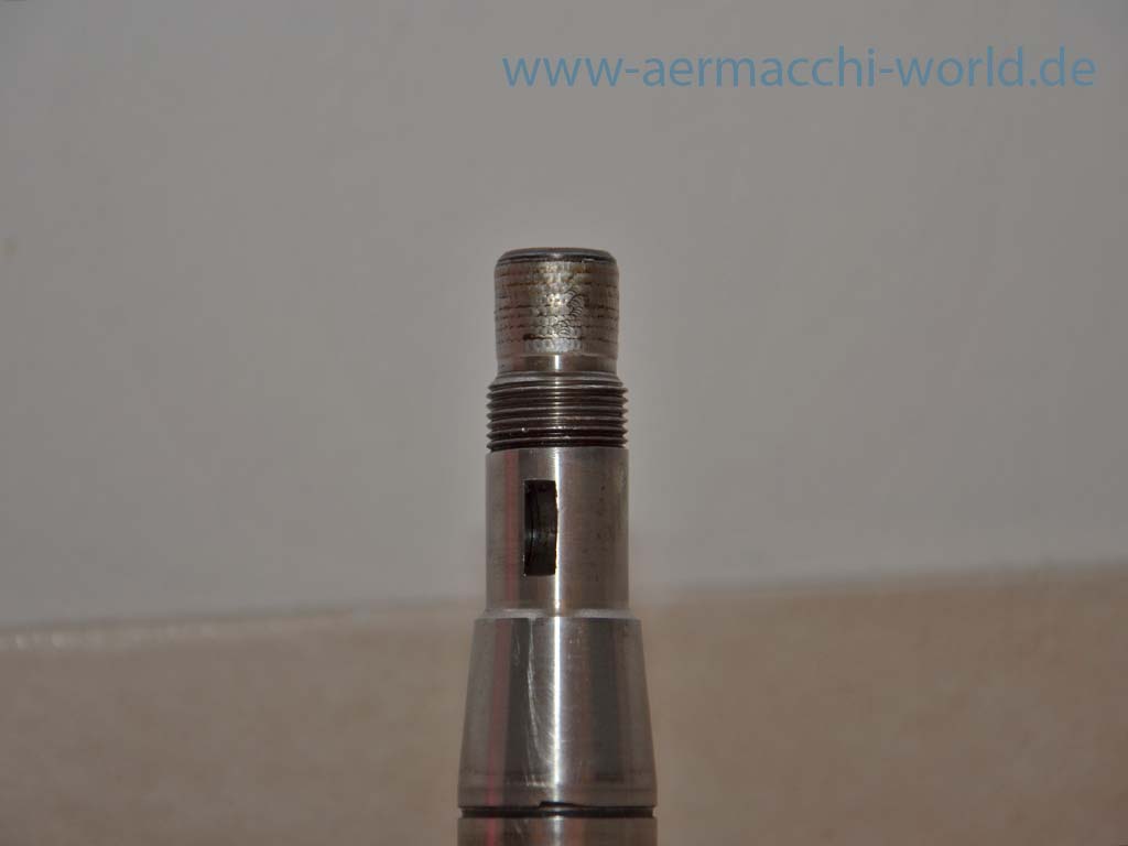
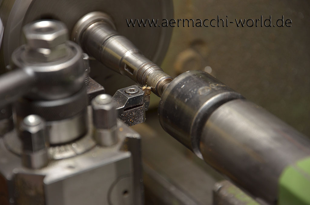
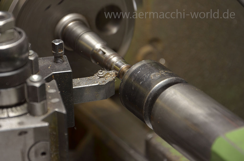
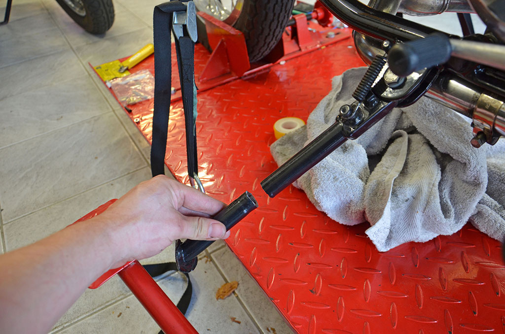
As I couldn’t find a correct steering lock for the Aermacchi I tried my luck with something that looked similar and made it fit with a lathe. Surprisingly it worked on the first attempt.
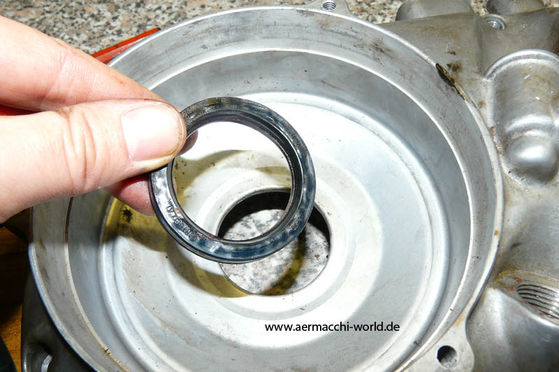
New seals for the carb today.

Paint code MG645.30 Standard Glasurit 90 CPS2

Before you start:
There is no guarantee for the correctness of the information provided. That following steps describe the procedure for my 1970 GT-350. It’s a different procedure on other model years!
To my knowledge (again, without guarantee) this is valid for 1969 to 1972 Sprint 350cc street bikes and not for earlier bikes and not for the 1973-1974 electric start!
Please ailways use a few drops of oil to fit the parts together.
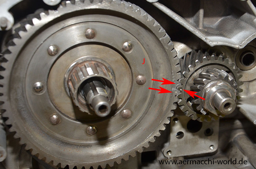
 Pic 1.
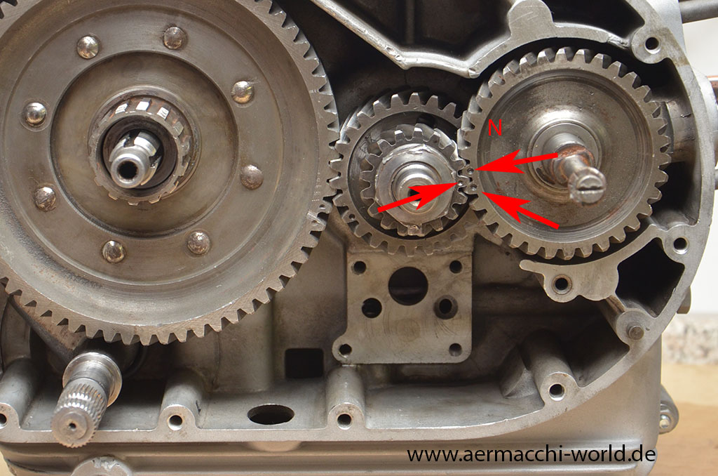
 Pic 2.
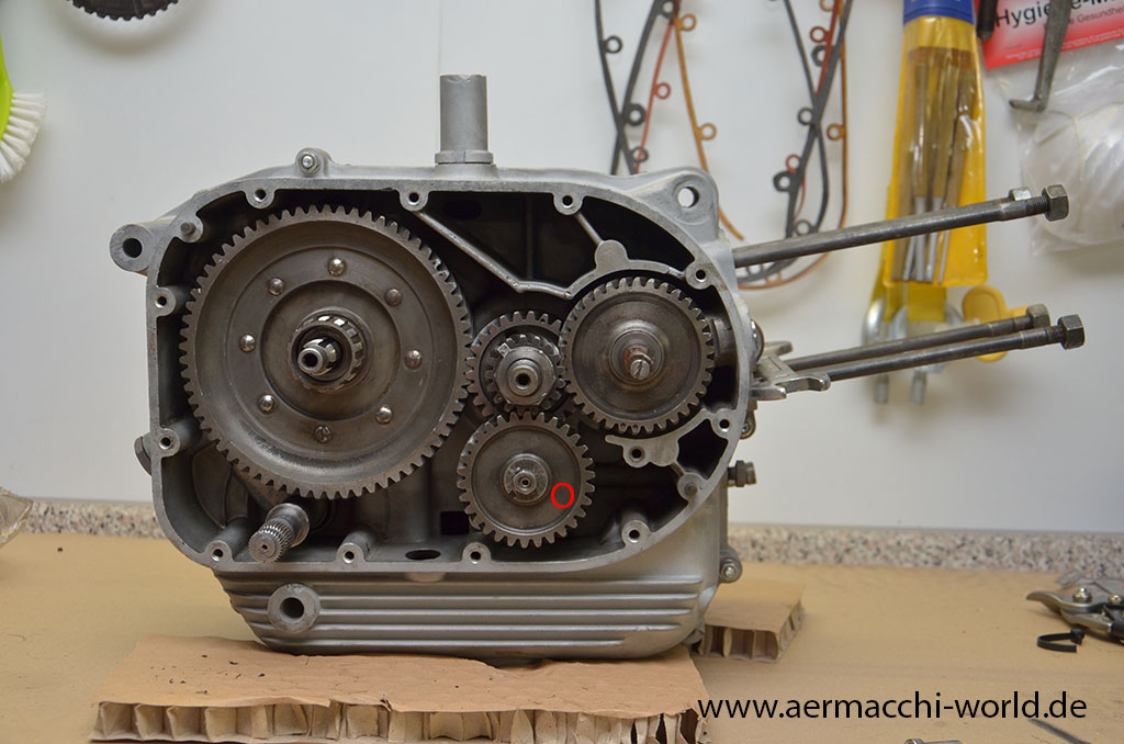
 Pic 3.
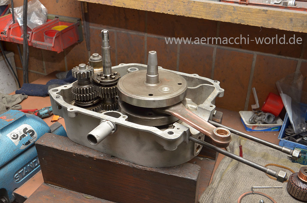
 Pic 4.
 Pic 5.
 Pic 6.
 Pic 7.
 Pic 8.
 Pic 9.
 Pic 10.
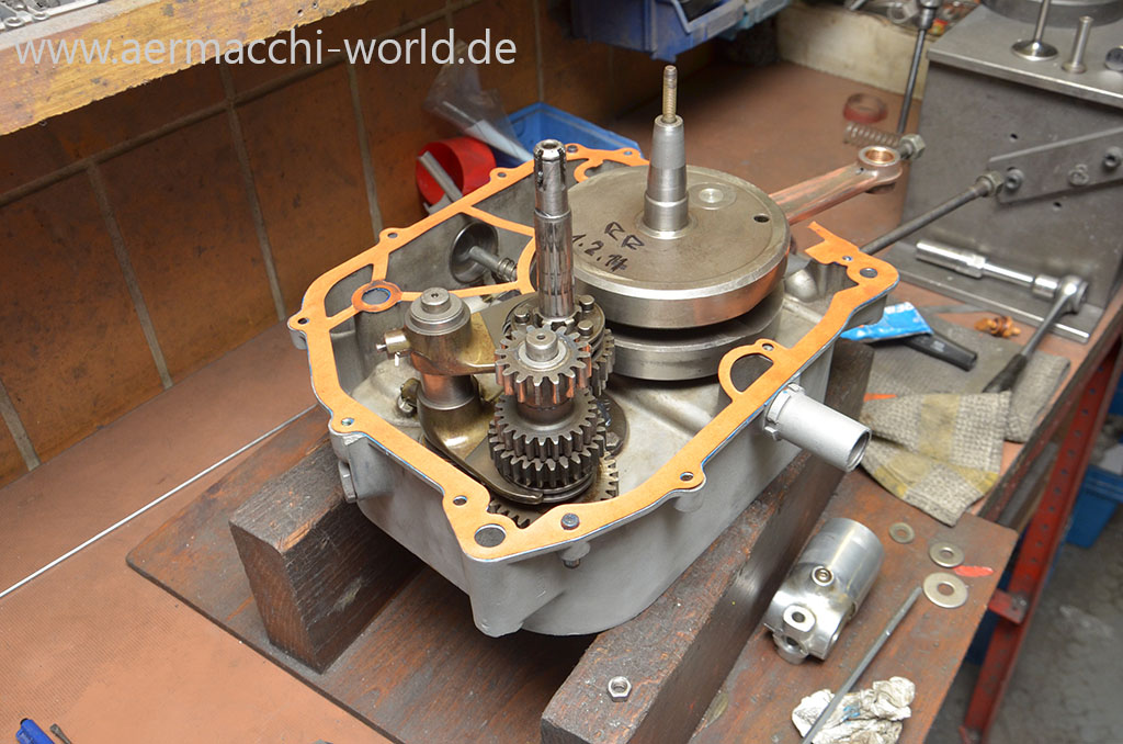
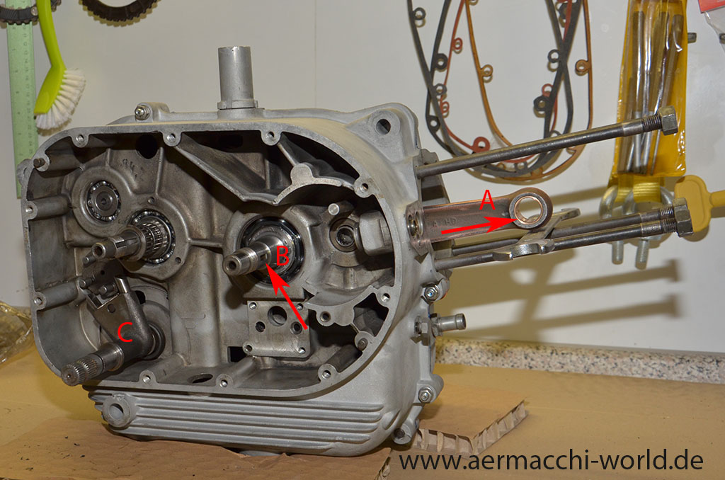
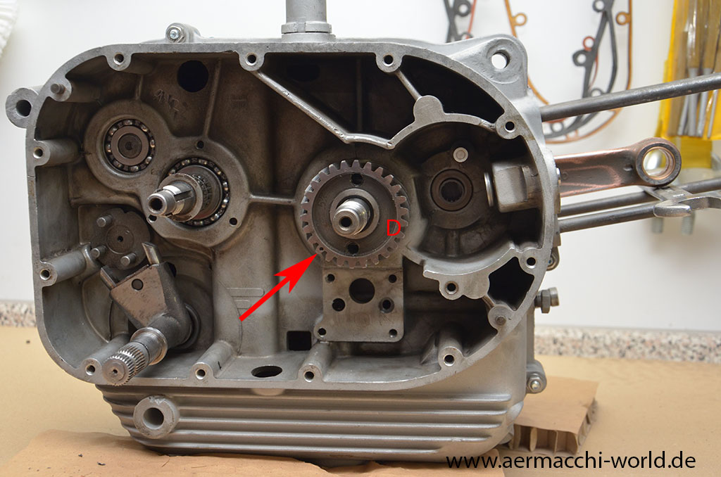
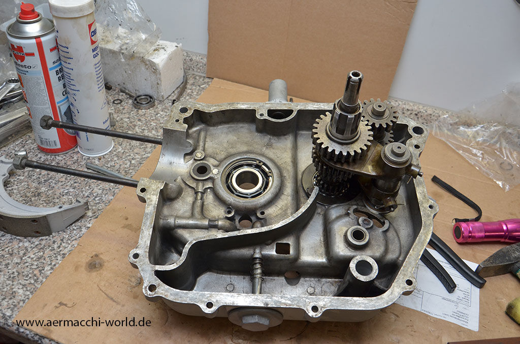
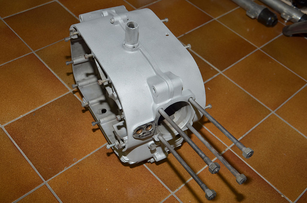
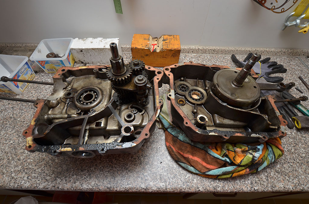
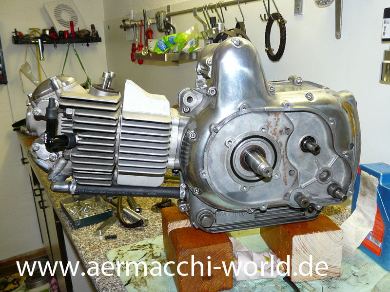
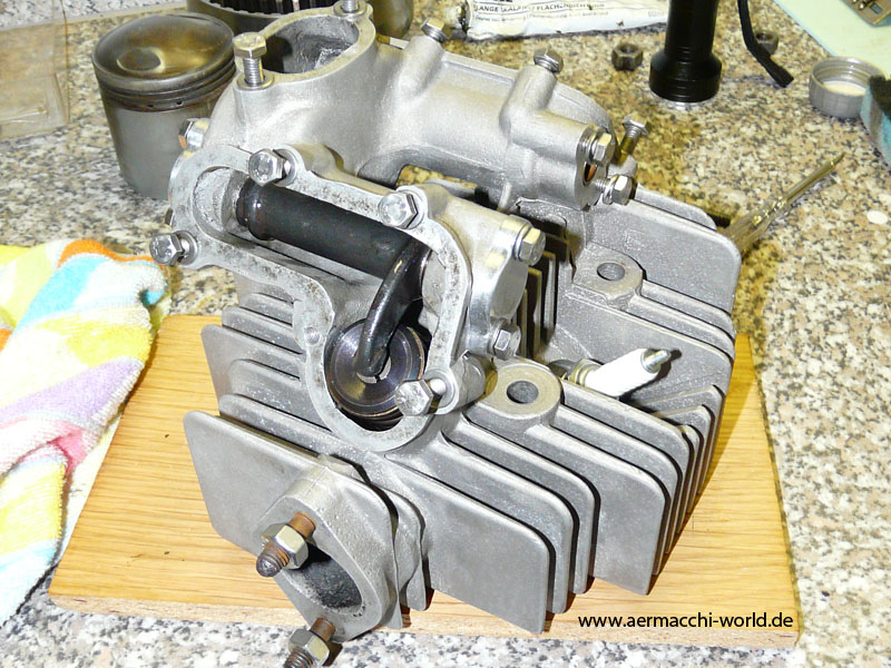
Everything within factory specs now and putting engine cases back together.


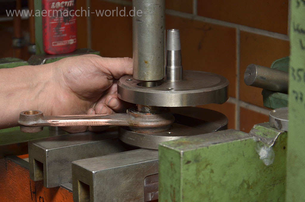
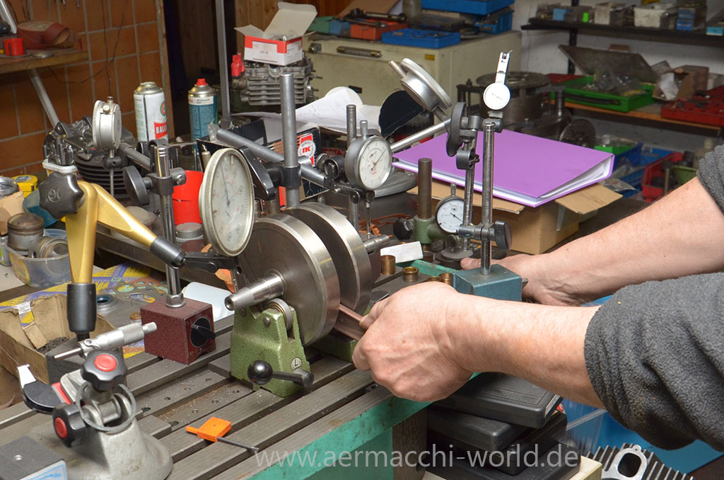
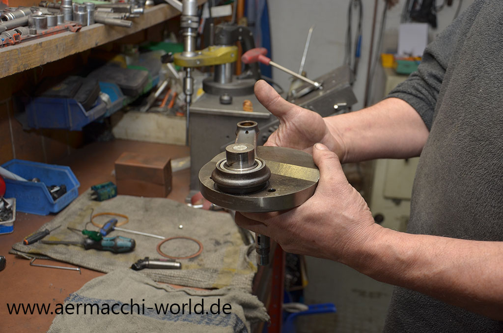
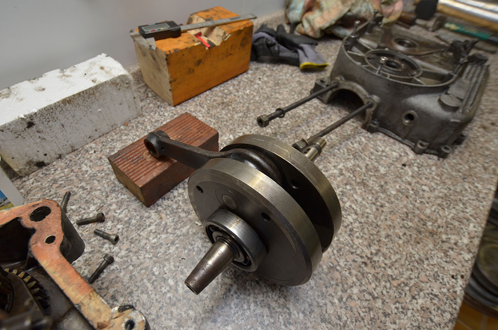
The new ballerings, the new rod and the overdone flywheel getting back together. Rudolf than trued the flywheel to 0,01 mm which is much better than factory Defaults.
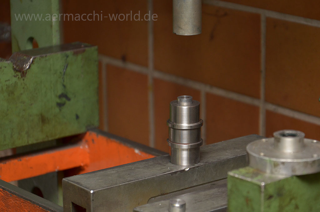
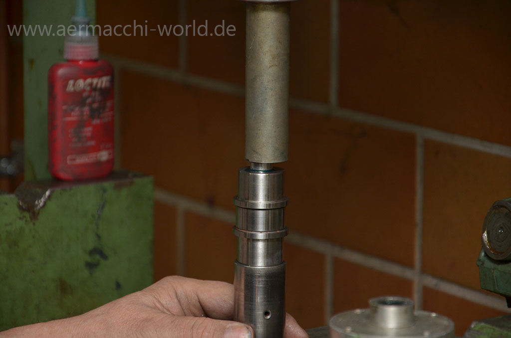
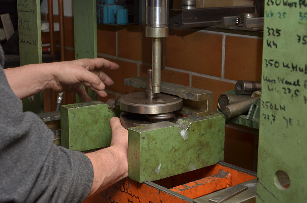
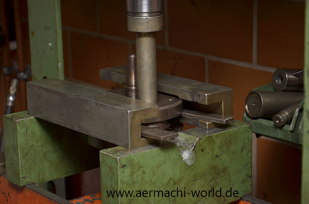
Pressing new plugs into the crankpin and than pressing the crankpin into the flywheel with copper paste. You need about 5 tons of pressure for this.


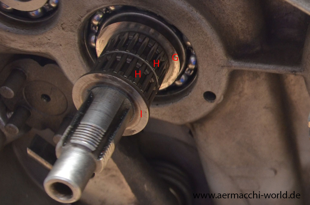
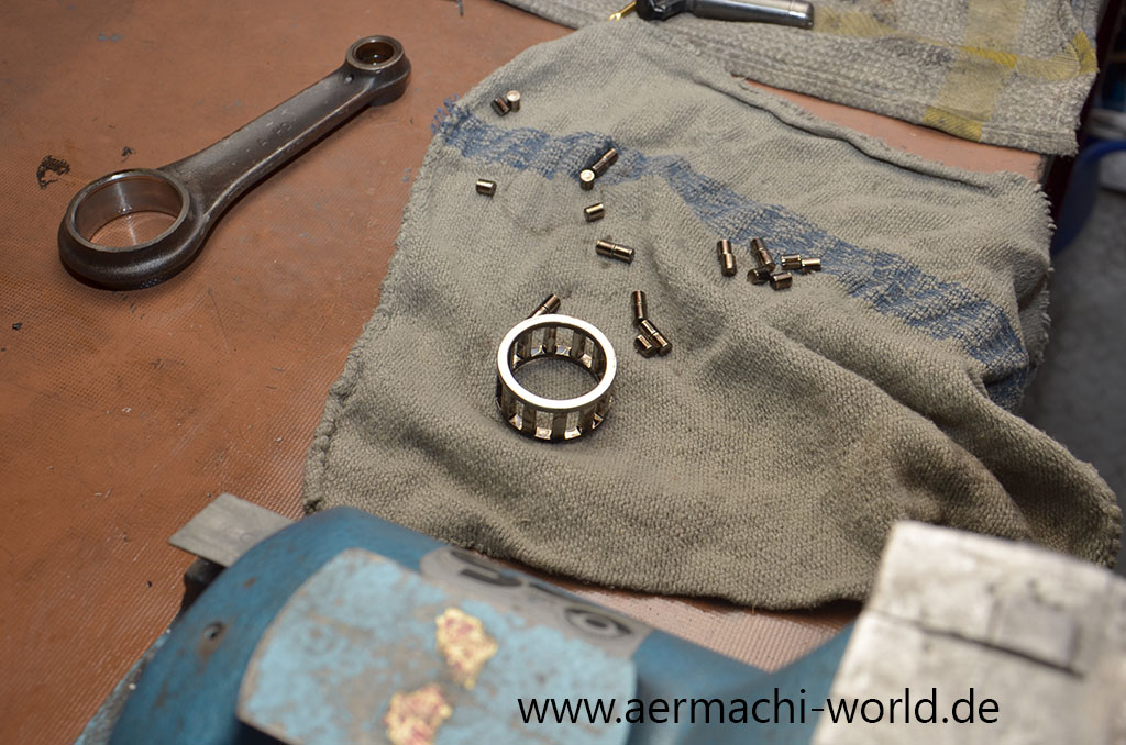
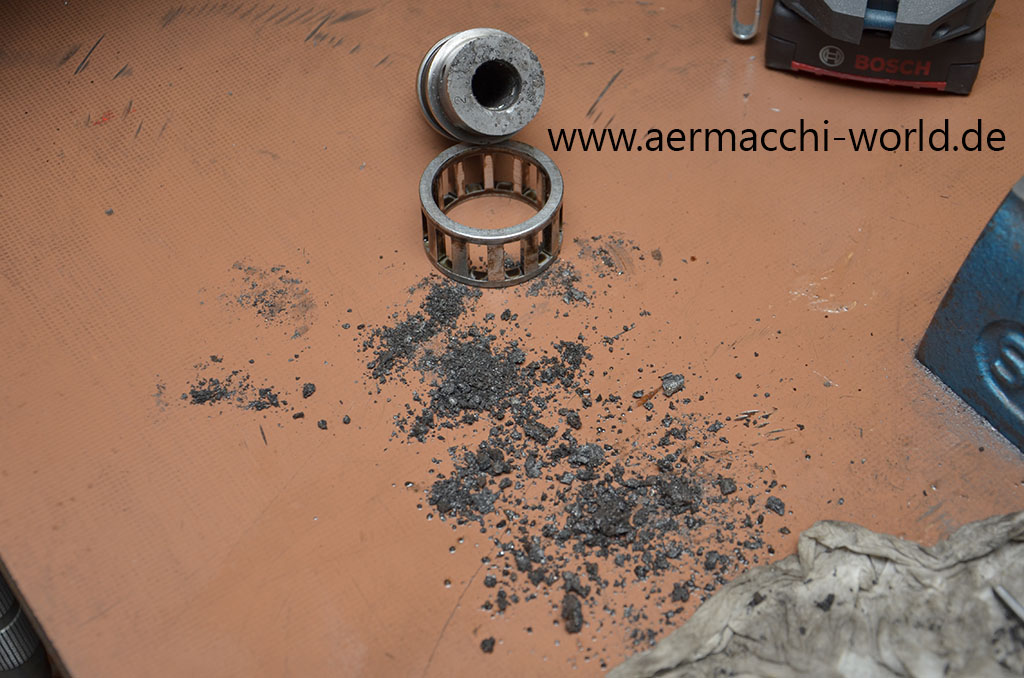
We polished the crankpin so the new bearings do not have to cut off material. The original bearings which consists of two parts rollers in each cage we replaced with “one-part only” bearings as you can see on a later picture.

You can see some marks on the left shaft of the flywheel. I gave it to a laser welding specialist who added some material. Later we took the material off again on the lathe and the result is a very nice and smooth shaft within the tolerances of a new shaft.
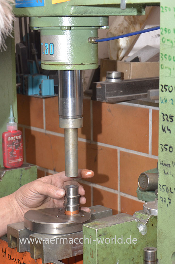
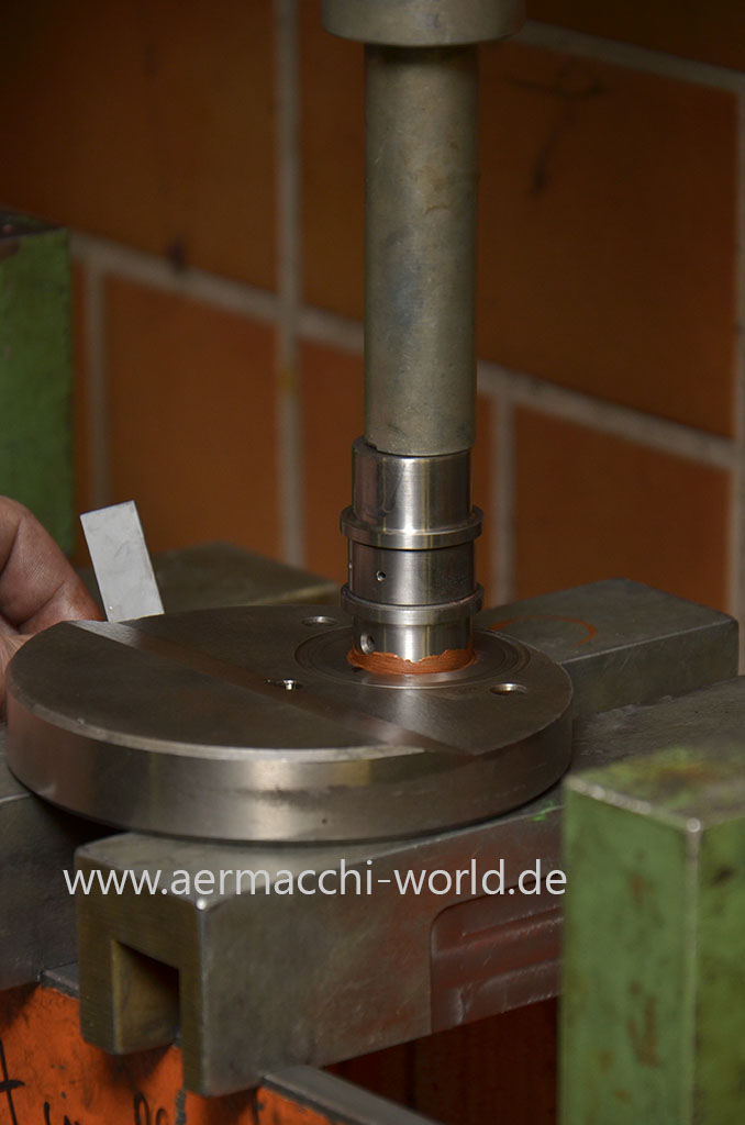
Here you can see how we pressed the crankpin from the flywheel and the oil dirt we found inside the crankpin after drilling out the plug. This is a typical 4-Stroke-Aermacchi problem and the reason you really should change the oil once a year or every 1000 miles. Rudolf decided the rod is used up and that I will need a new one.
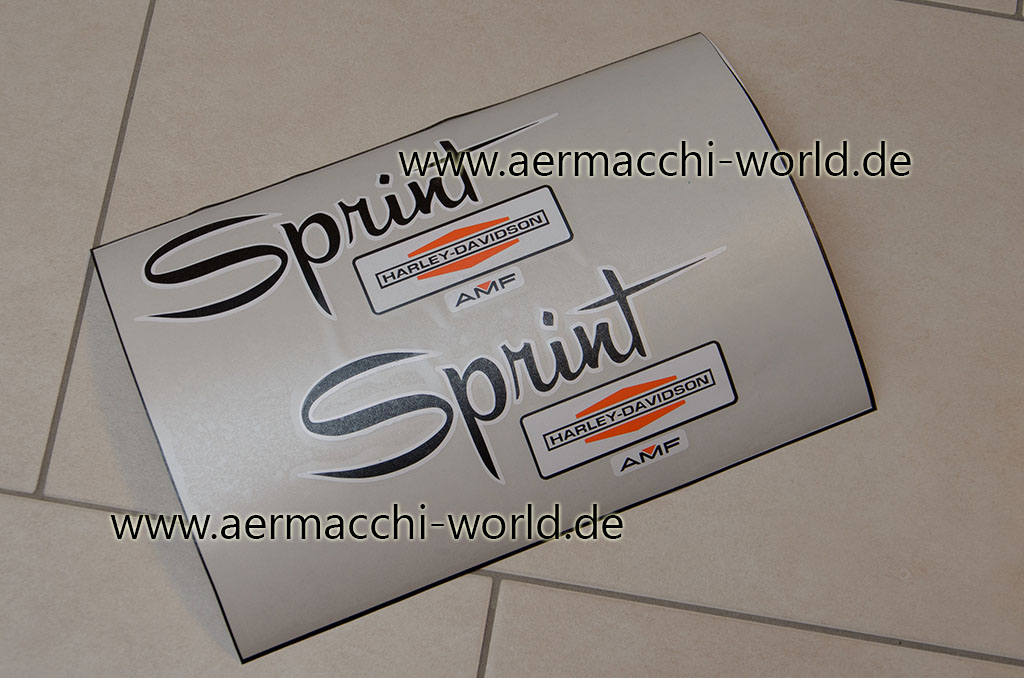
While waiting for the paint job to be completed I have reproduced the gas tank decals as vinyl stickers. These are the 1971 design as I will go with the 1971 US design in sparkling green.
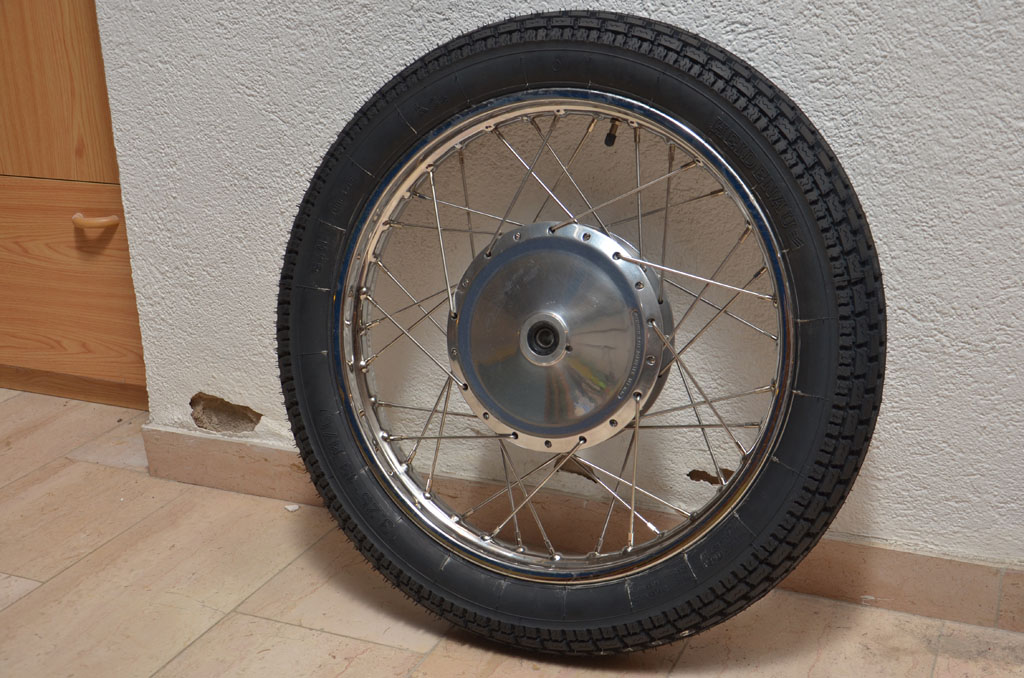
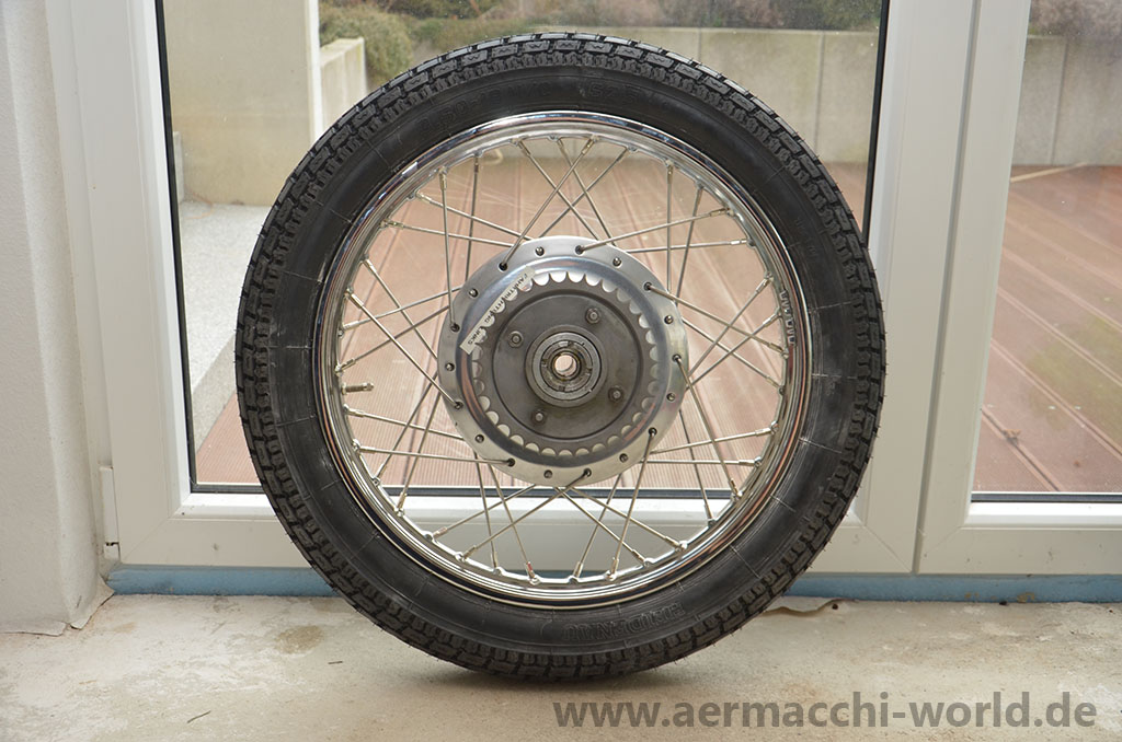
New tube and new tire, Heidenau K34 3.25-19

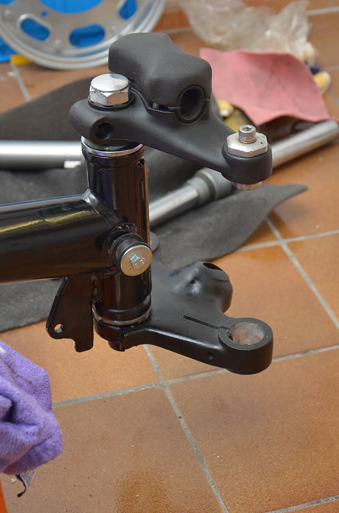
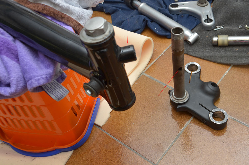
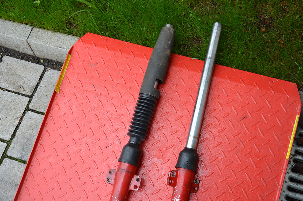
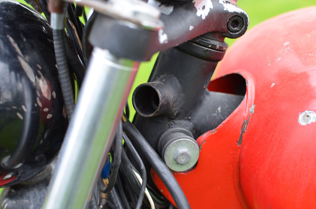
A lot of fresh grease and 50x new bearing balls (8854) for the NOS fork stem. The fork stem I got with the bike obviously got pressed together in the wrong way as the notch for the steering lock was on the wrong side.
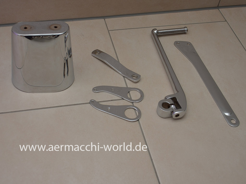
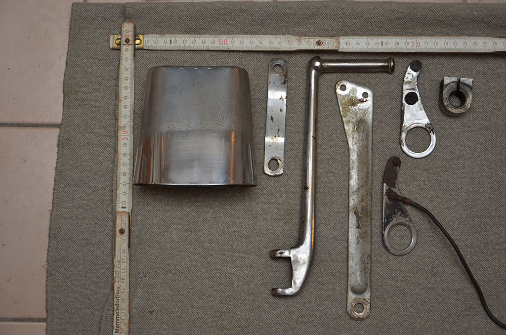
The parts shown on the last picture like airfilter housing, kickstarer and some other stuff went out for rechroming that day.
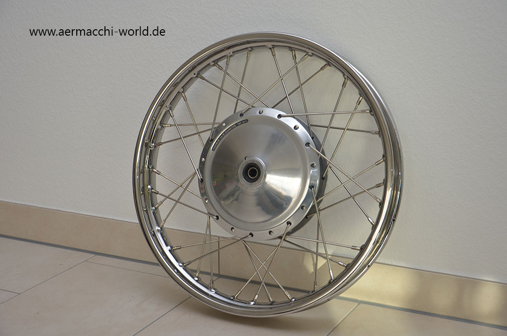
Brand new rim and new stainless steel spokes


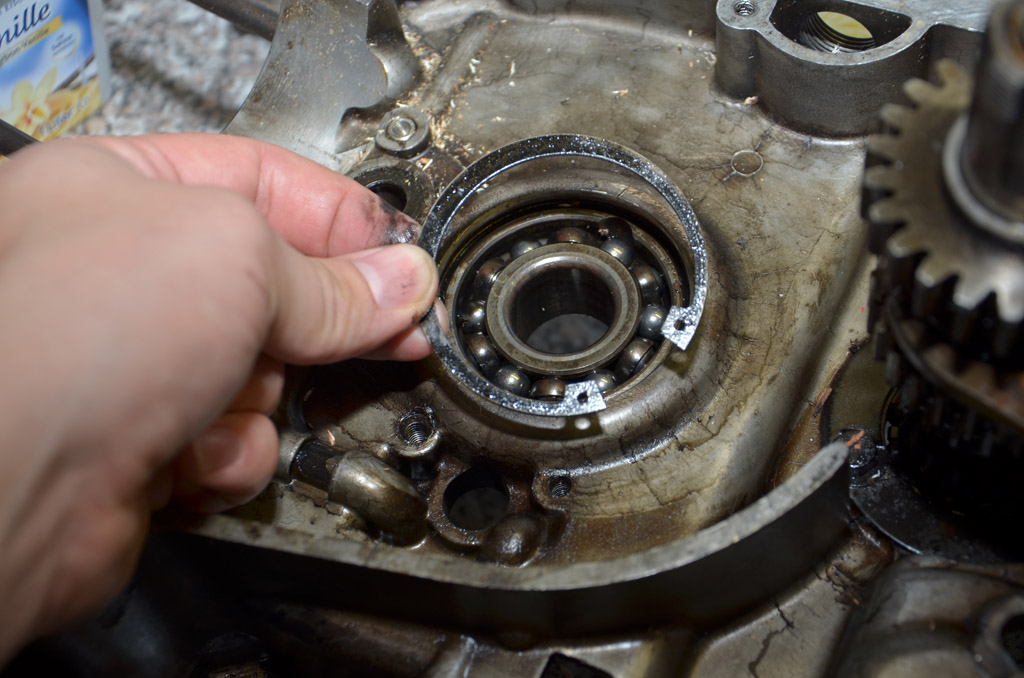
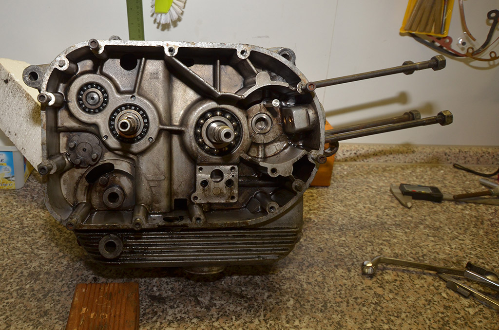
I have replaced every bearing in the engine case with new ones. The front wheel hub is also redone and waiting for new stainless steel spokes and a brand new 1.85×19 front rim. I have also replaced the bearings and the dust seals here. At the moment I am working front fork.
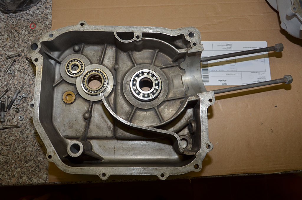
Left to right: 98302, 16006, 6305. Tony Foale suggested to use C3 bearings for the flywheel (3305 and 6305) and so I will do.


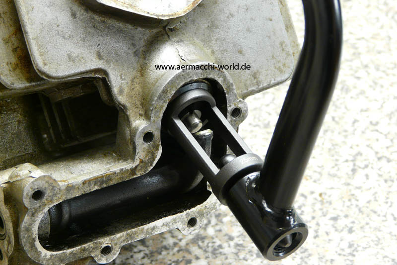
I needed help from a machine shop to get the large doublerow bearing out of the right engine half.
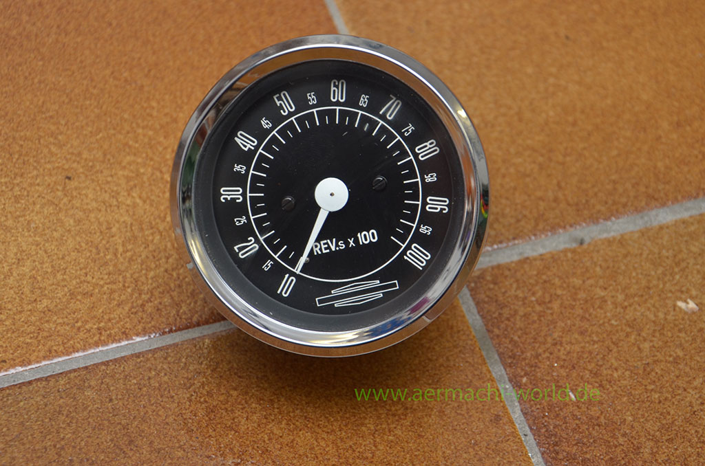
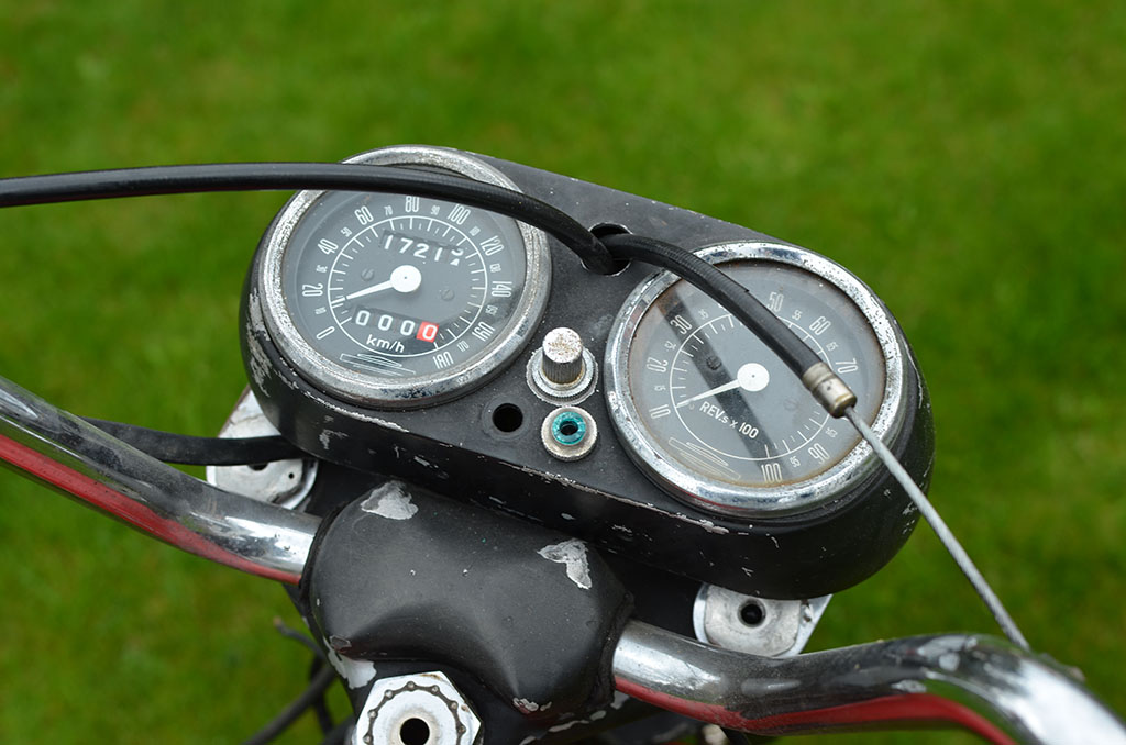
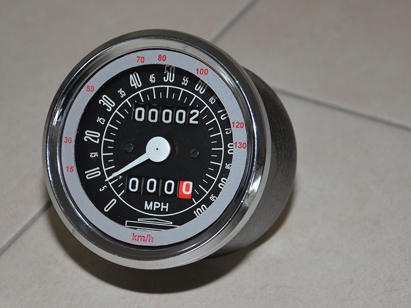
I found a NOS tach. in perfect condition for a good price.
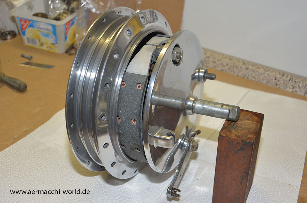
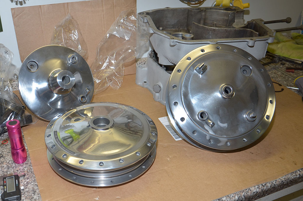
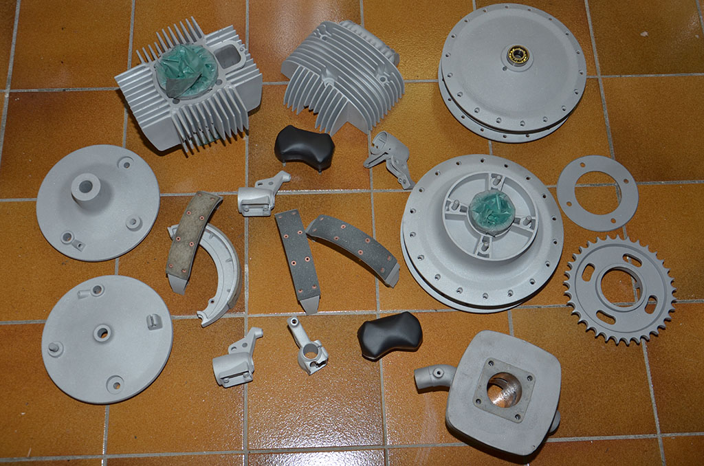
I also received back a first pile of parts that have been corund blasted in the meantime. The wheel hubs will now be polished to shine as new again.


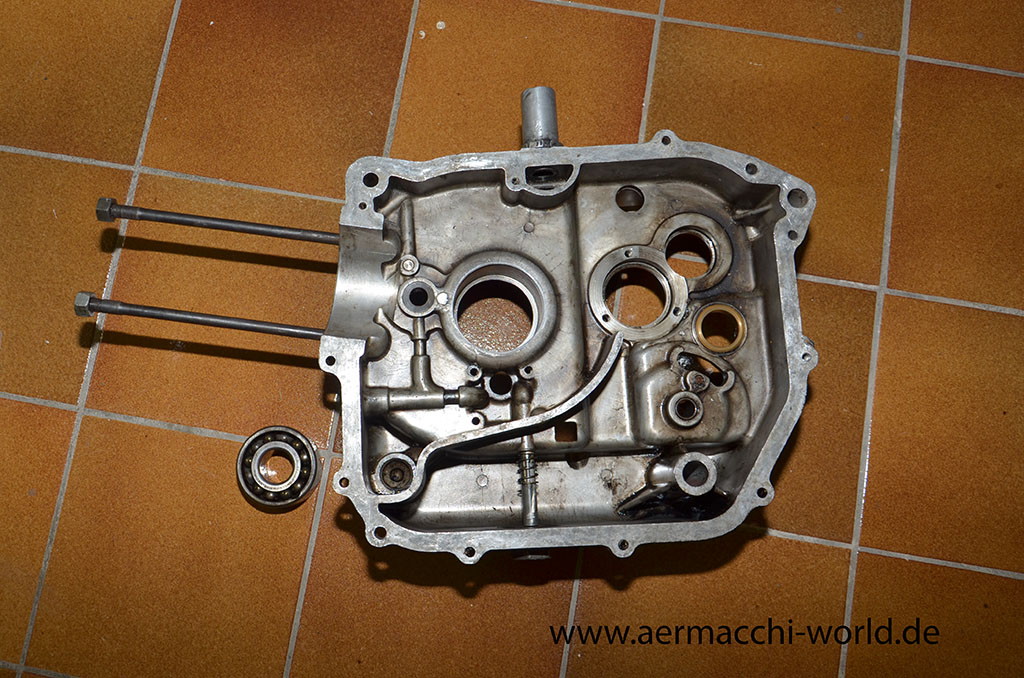
Oil seal 15x24x7. In a later right side cover (71) it is 15x32x7
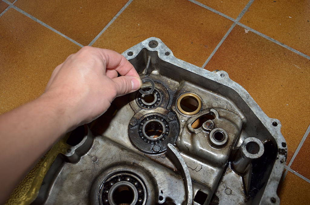


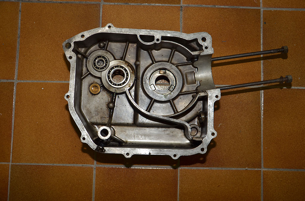

Smaller bearing for Transmission in both sides of the case. 15x40x9 mm. One was marked x98302 KH SRO. The other was just marked Made in Italy and something I could not read like PVR AVP. Don’t know.

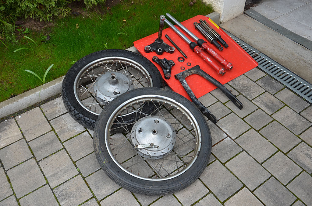
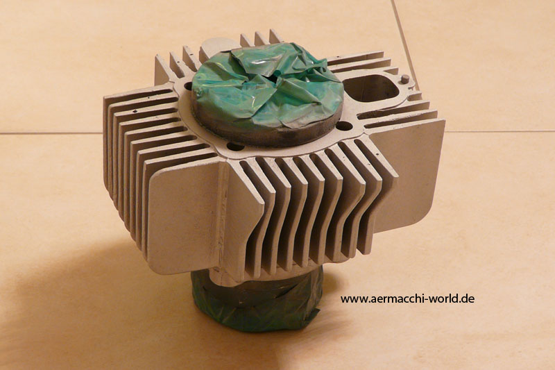
The wheels are totally disassembled. I will give them out for cleaning (sand blasting) and I will probably have the hubs polished. Cylinder head and barrel will also be sand blasted.
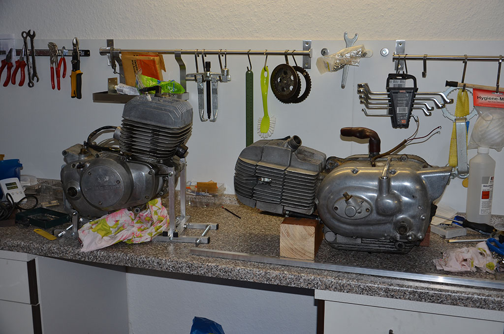
Yes, there is a X-90 cylinder head also on this picture. 😉


double row ball bearing for crank in right engine half: 3305 FAG O.B Germany. Size: 25x62x25,4mm
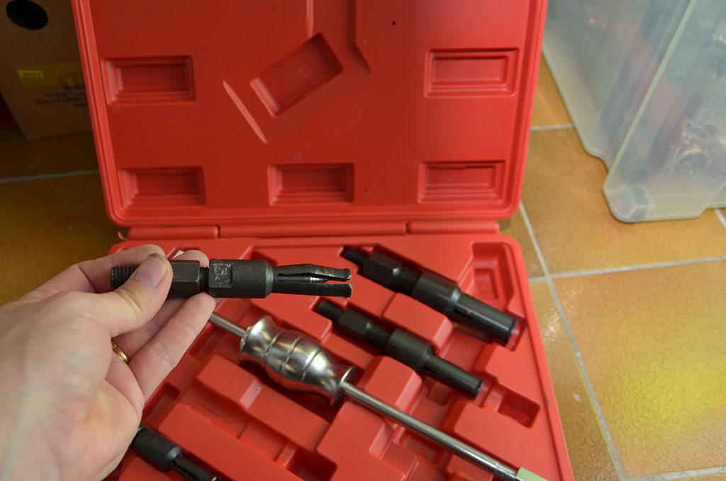

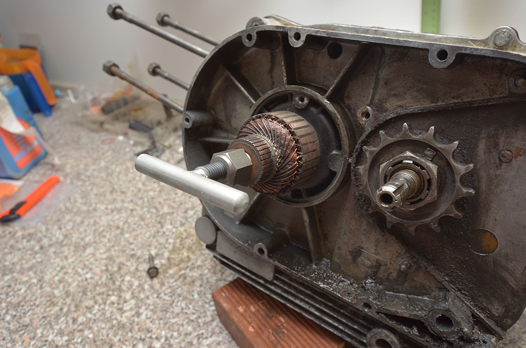
I bought a cheap tool set to remove the ball bearings from the engine case (left picture). I totally regret it. It was a waste of money. The tool is from a much to soft metal and it bends while the bearing still sits tight. I now own a professional bearing puller that worked like a charm.
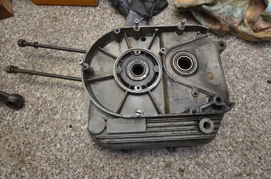
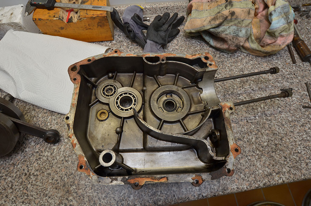
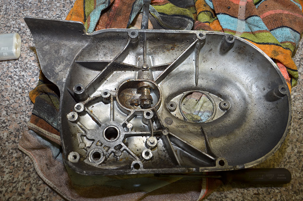
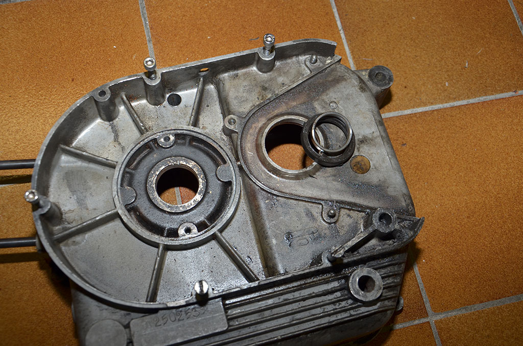
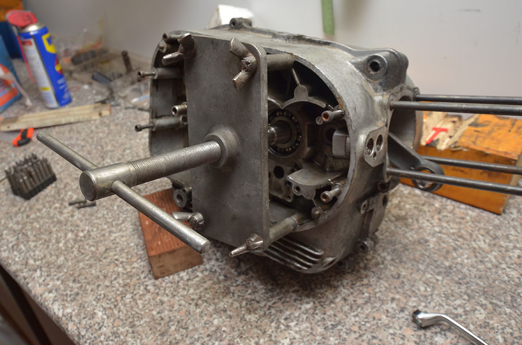
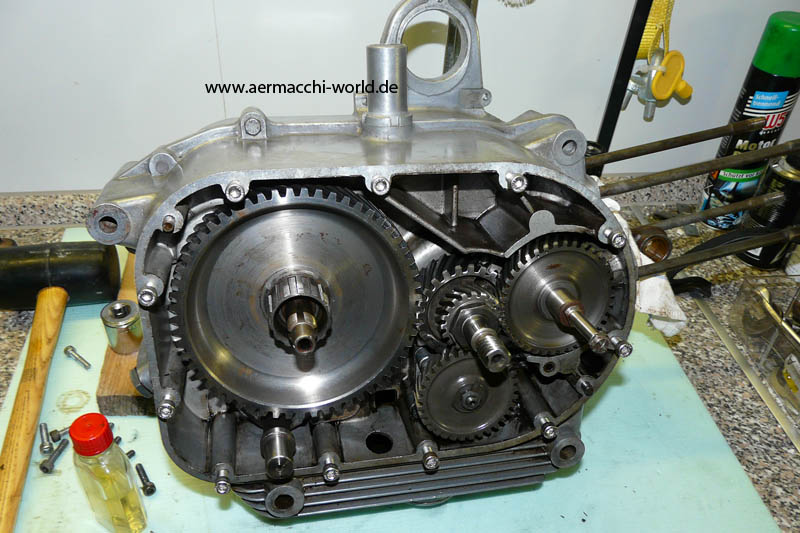
The engine case is open now and it looks like I did no damage. *Happy*
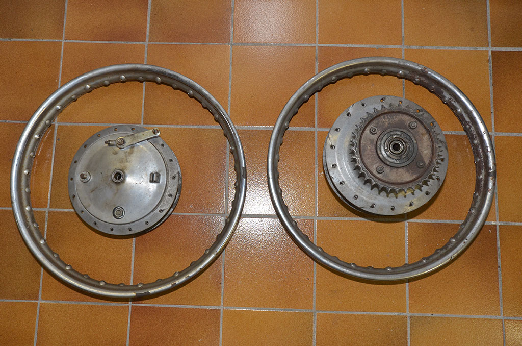
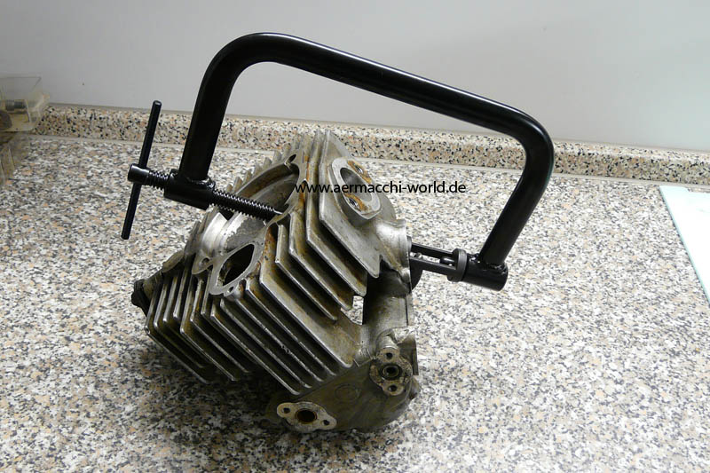
I will discard the wheel rims and buy new ones as re-chroming them would be more expensive and Radaelli rims are still available today. Thanks to Moto Italia I also now own a engine split tool.
Almost ready for splitting the engine.
Now tool for my Aermacchi-tool-collection. 🙂
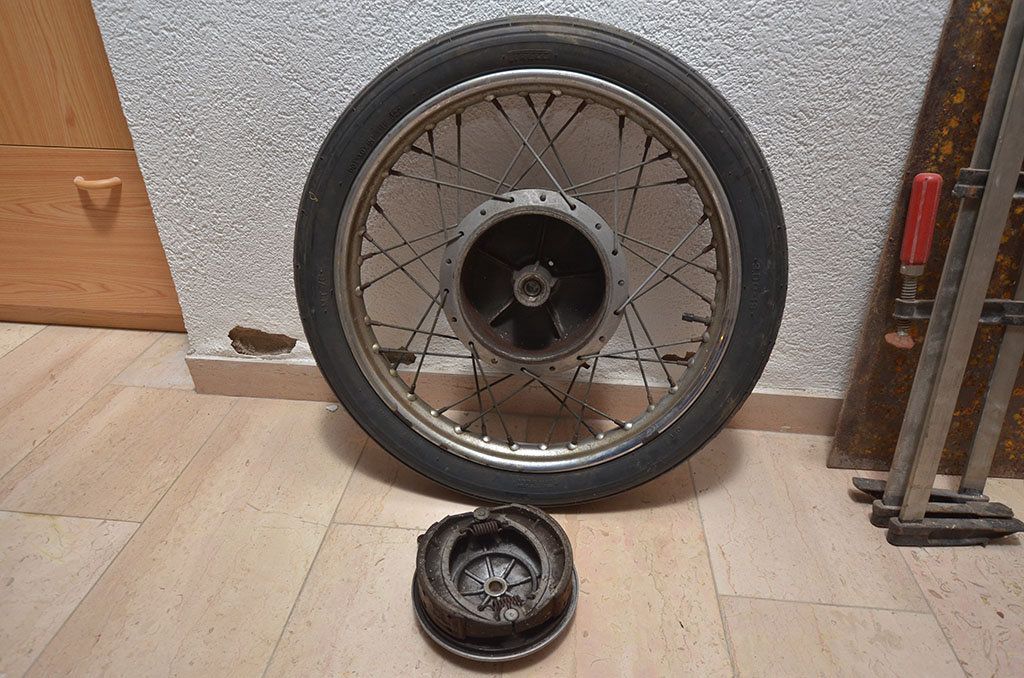


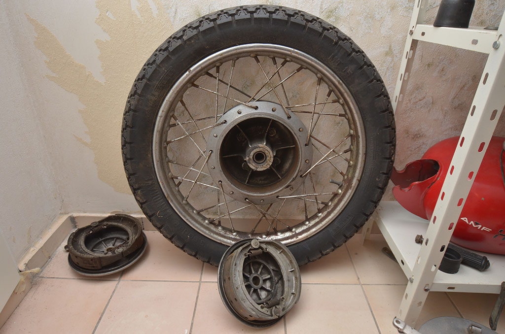

Before disassembling. Rear wheel bearings: SKF 6204-2RS1
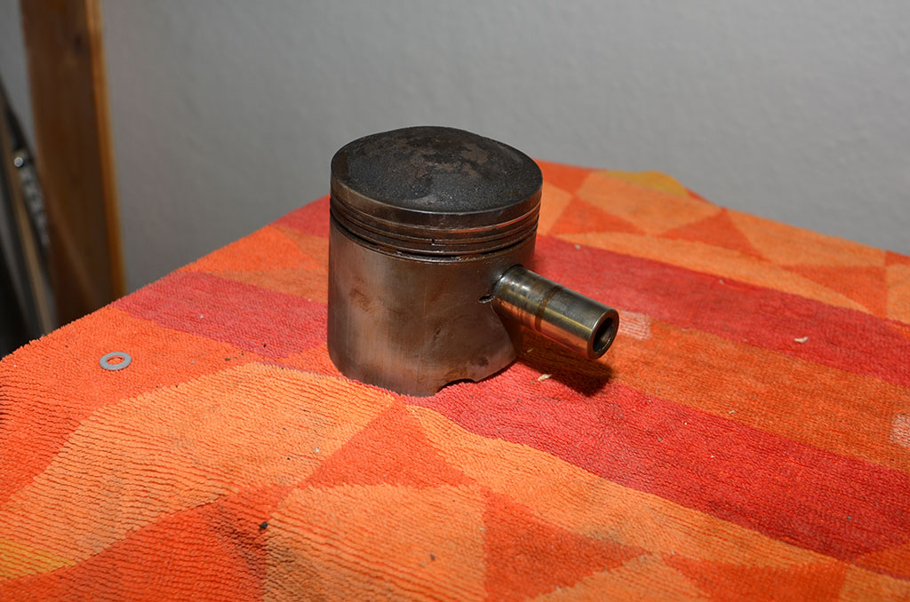
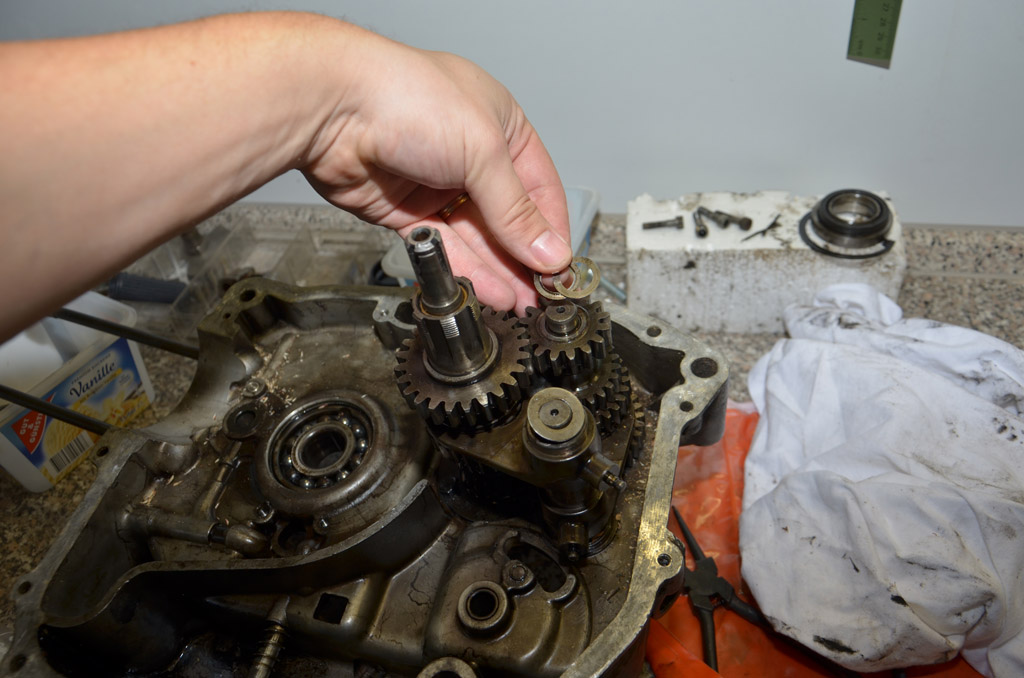
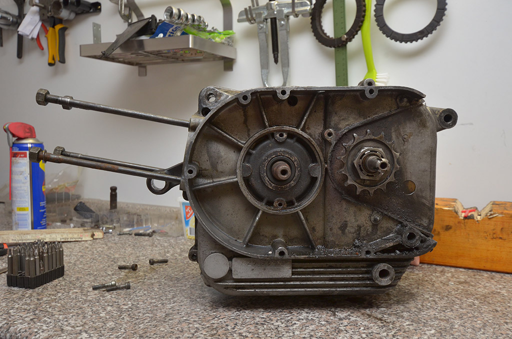
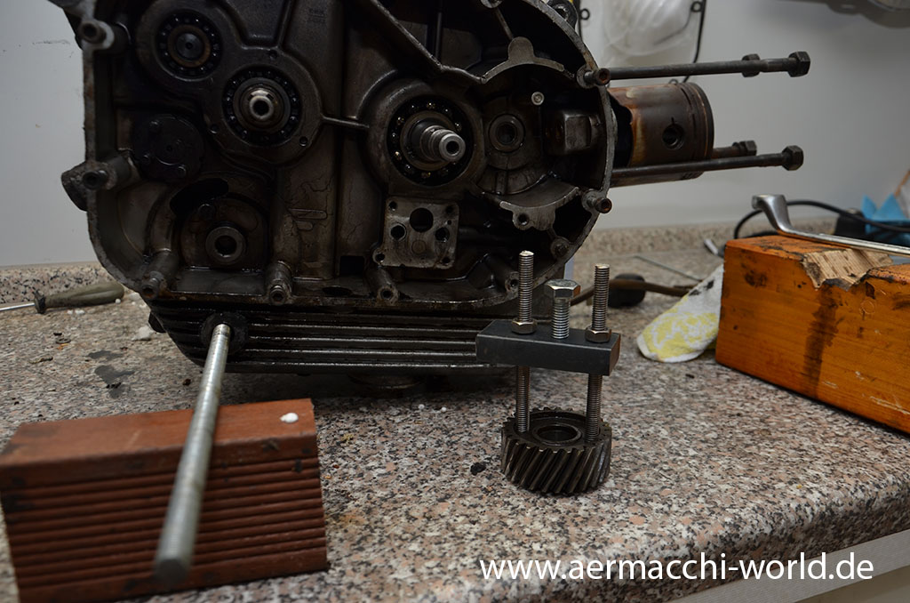
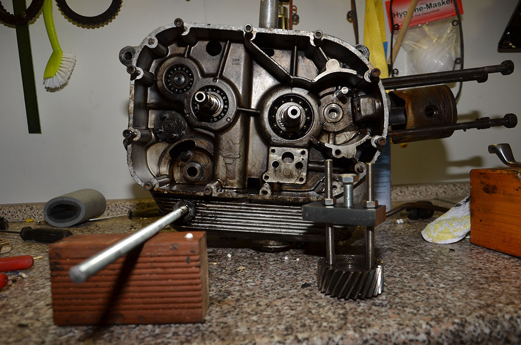
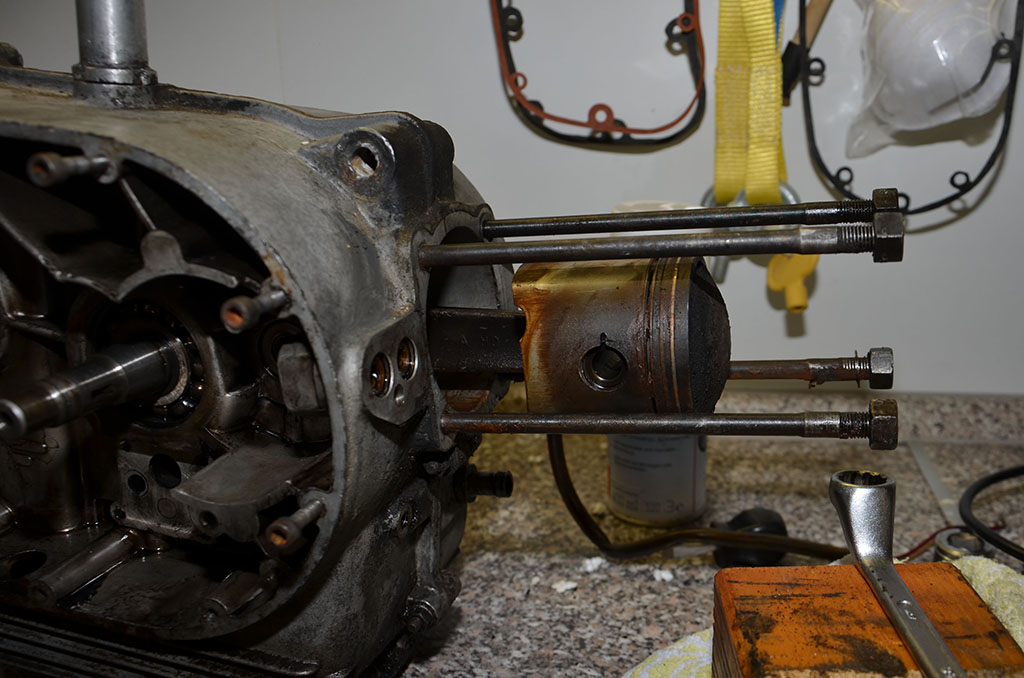
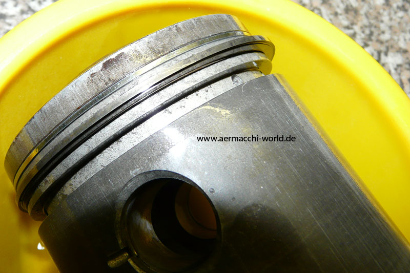
I built myself a pinion gear puller that worked good. As you can see on the last picture the piston rings are totally baked into the piston.
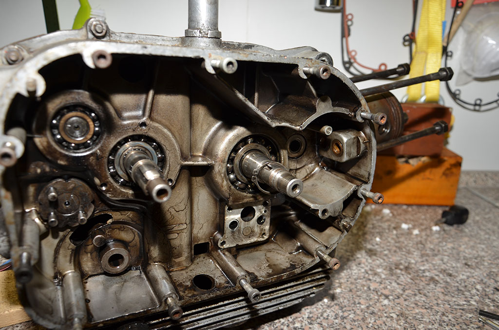
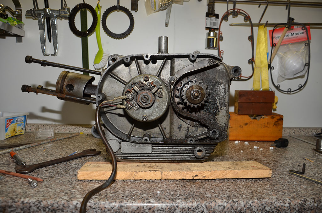


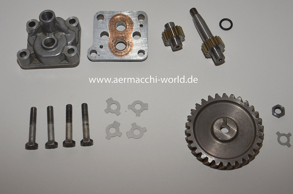
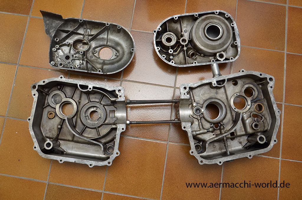
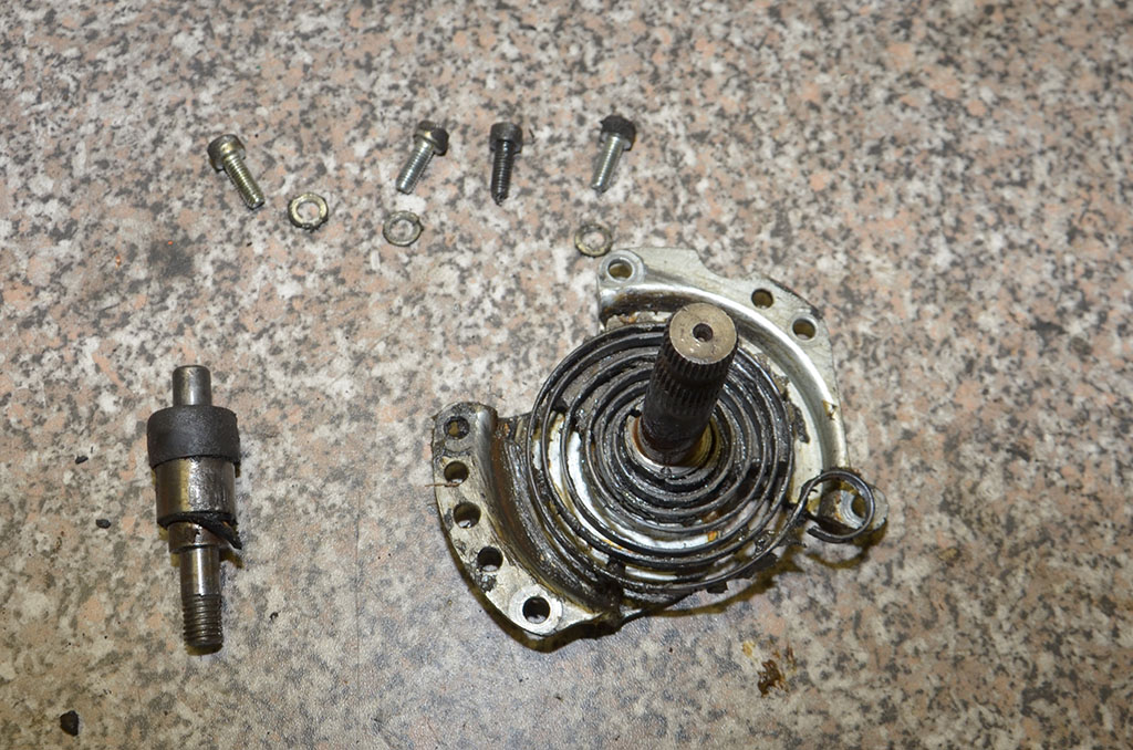
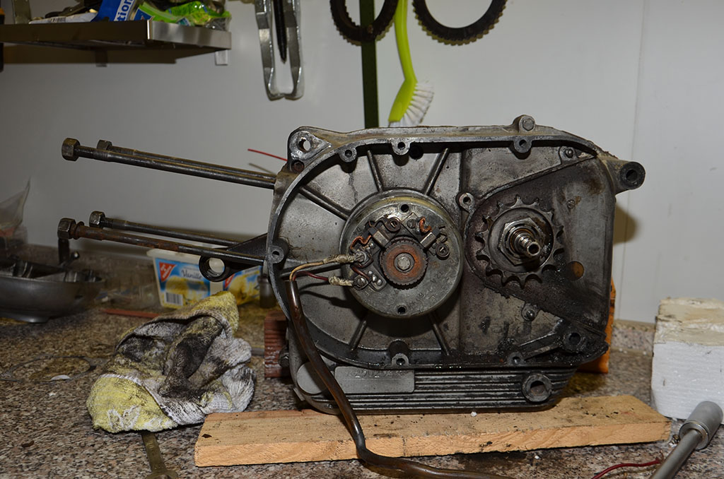
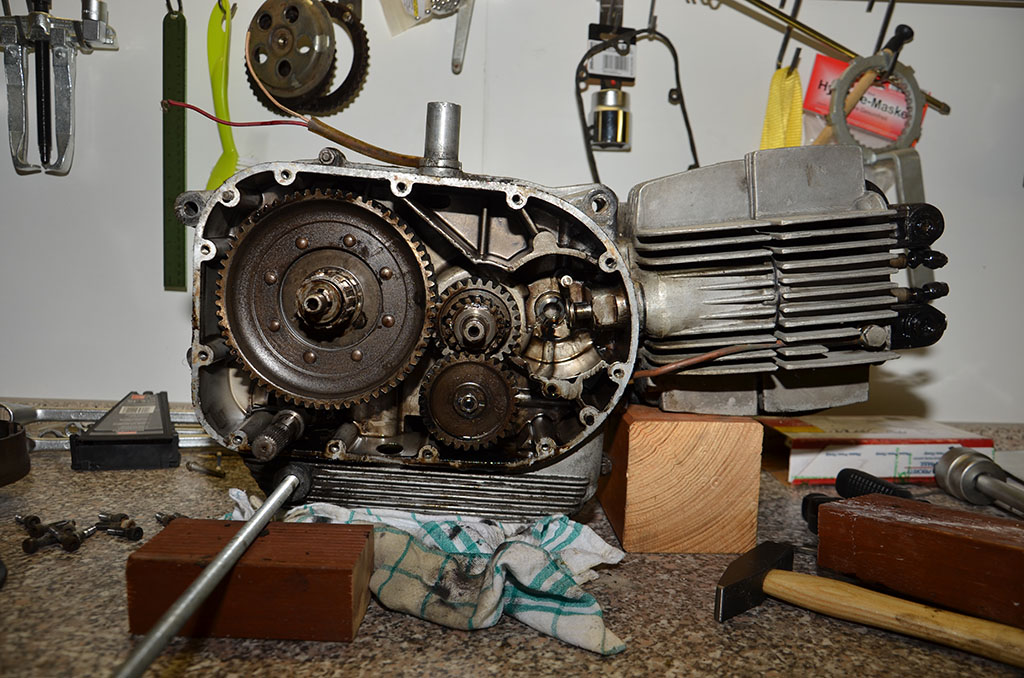
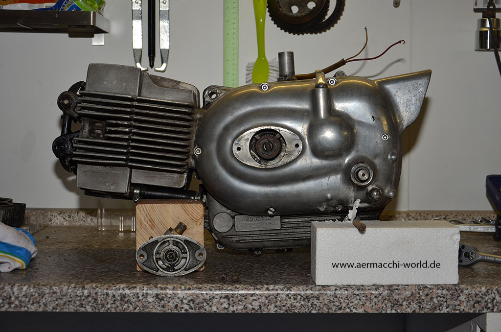
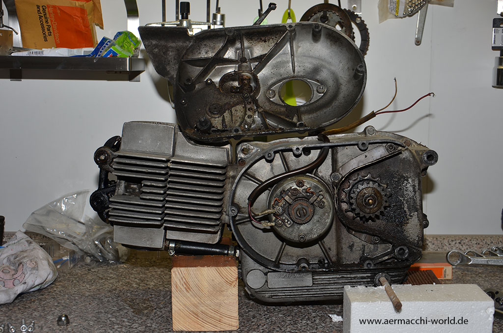
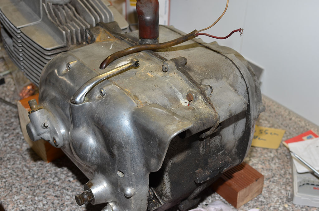
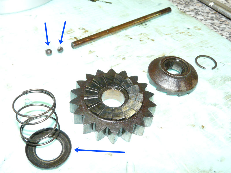
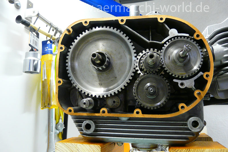
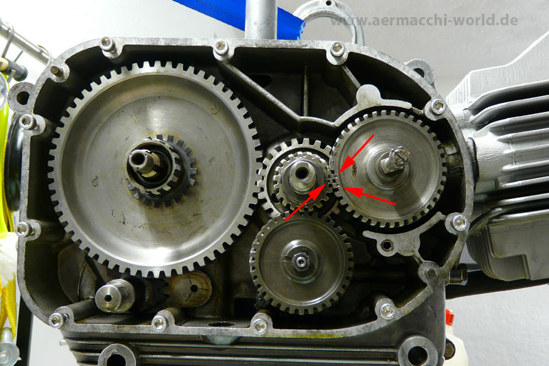
The inside of the engine looks not very good at all. Spark advance is broken and the primary gear is totally worn out. I am pretty sure more bad surprises will come, going deeper into the engine. I also noticed that the left engine cover has a 1971 production time stamp and the right side a 1968. I am pretty sure someone had the engine disassembled before me.


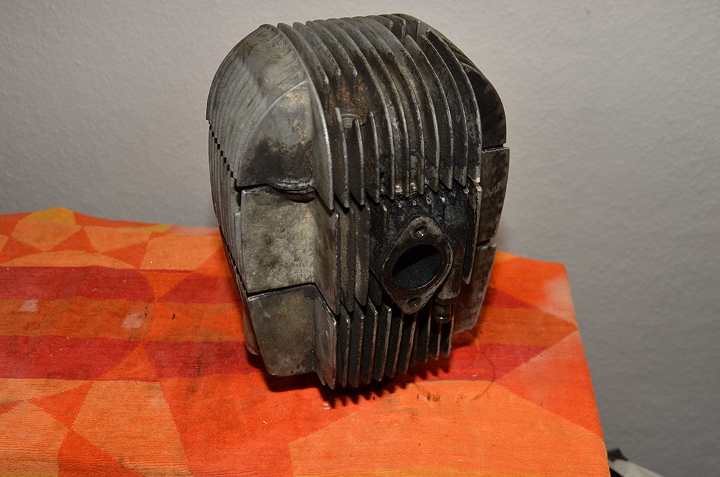
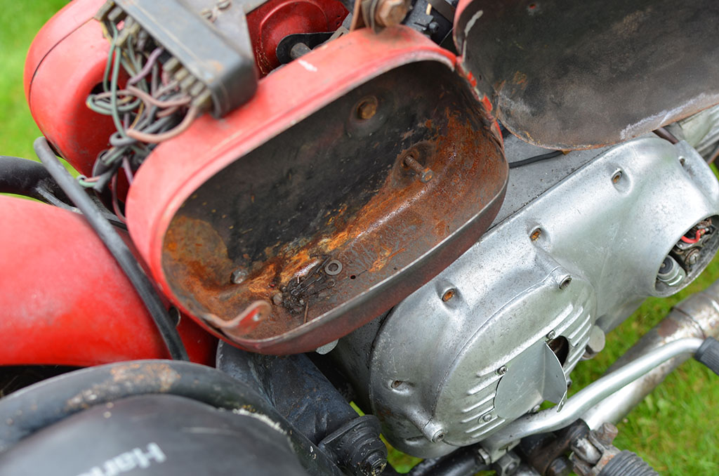
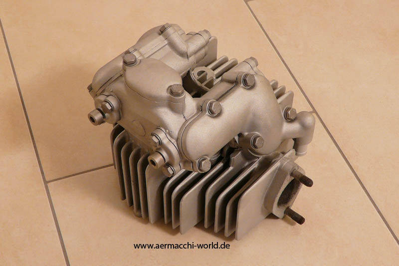
The engine is the so called “ashtray head”. The cylinder and head are designed for the US market. It replaced the earlier, classic Aermacchi cylinder/head. Customers in Europe didn’t like that design much and so it was available in Europe just for a short time period from 1969 to 1970 before they changed back to the classic knucklehead with the 1971 models. In US they kept the ashtray design until the arrival of the 1973 model of the Harley-Davidson Sprint.
Engine crankcase: L988
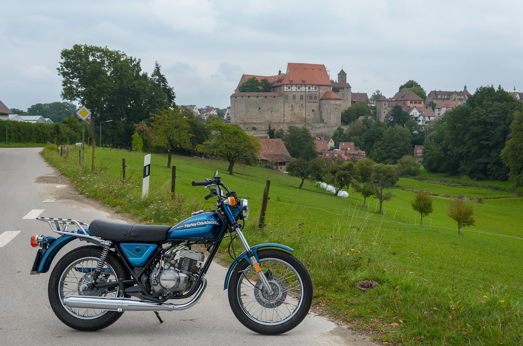
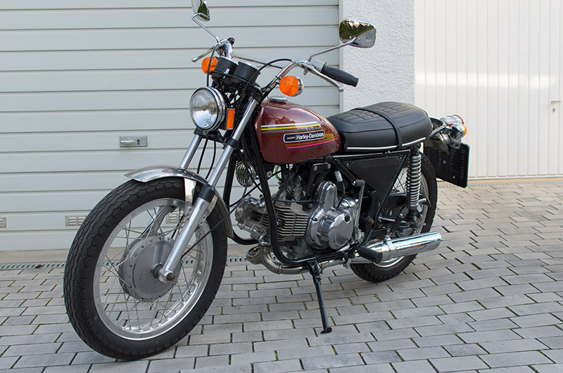
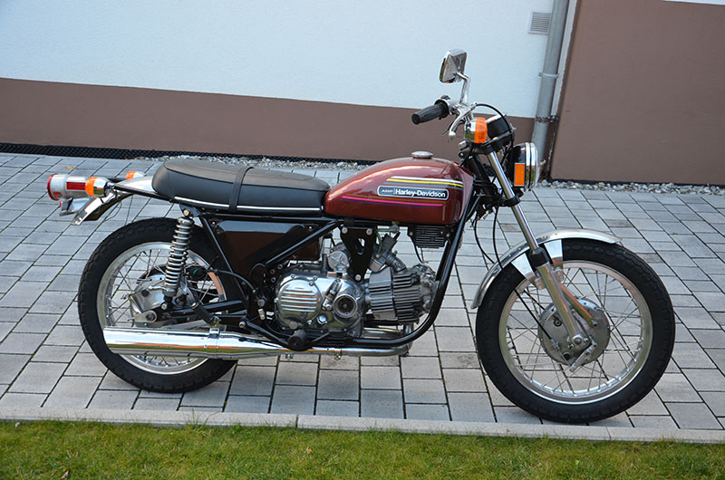
Finally back on road. I also bought myself a matching italian-flag-design helmet for the bike. 🙂


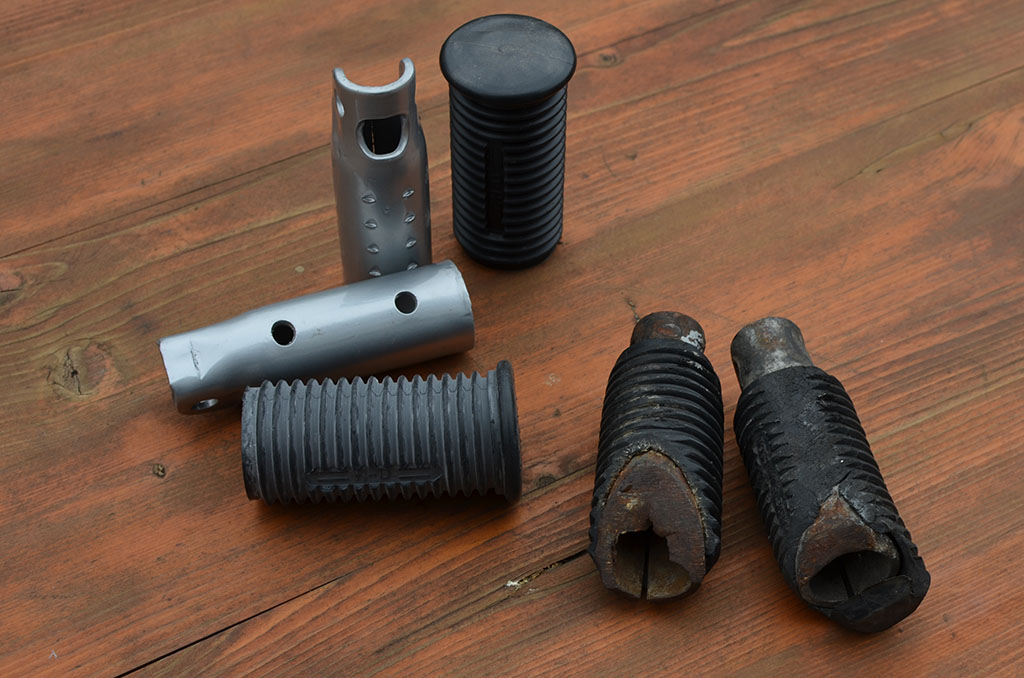
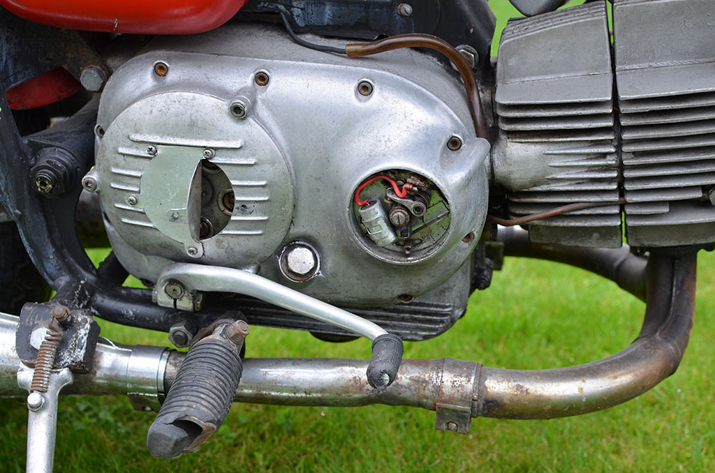
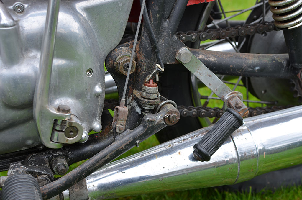
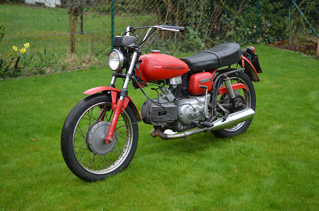
The GT once belonged to a fast rider. Those footpegs tell the whole story and it fits well into the picture together with the modifications made to this bike with a later and lighter seat, lighter tail light, missing fork dust-covers, cut-out clutch cover and other modifications – all with the goal of getting the bike as light as possible.
Because of the bad overall condition of the bike I assume the previous owner once lost interest in the bike and had it stored outside somewhere in a tiny Italian alley for decades.
Those footpegs will go directly into the trash bin. I have restored footpegs and reproduction rubbers in my inventory. The engine will get a good cleaning before disassembling and the airfilter will be replaced by a K&N replacement.

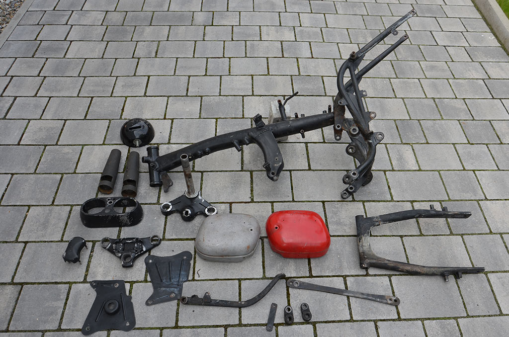
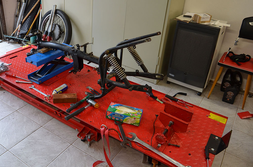
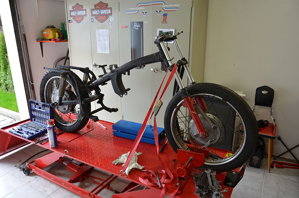
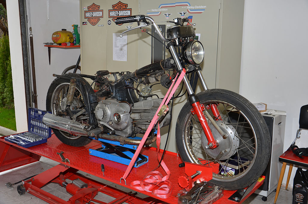
It is done, the bike is very handy now and easily fits into a large rack. The hardest part was getting the fork out of the frame. Heat and pure force did the trick. The weldseams look like having been done by an apprentice in his first year. Never seen such bad weldseams on my other Aermacchis.
The tires, rims and spokes will be replaced later. Hubs will be polished and reused. The oil in the front fork – or better what is left – is just mud, but there is hope that the fork may be repairable. The shocks are totally broken and can’t be reused.

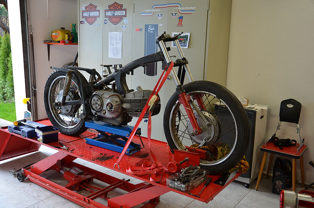
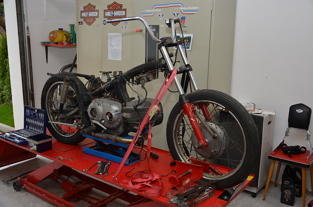
Getting the engine out of the frame was easy because of the original Aermacchi “backbone” frame. Somehow the engine also felt much lighter than the 1974 engine, but as I do not know the weight differences this is just a feeling.

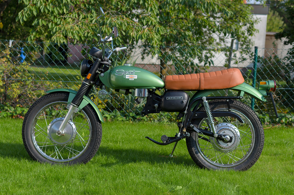
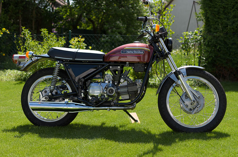
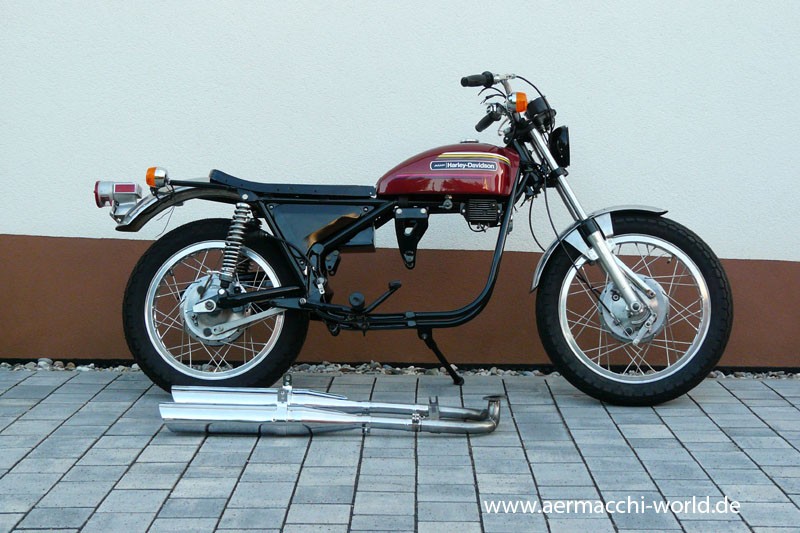
There – the idea of the cafe racer is back in my mind…
No, not this time. I will restore it to factory defaults. 😉

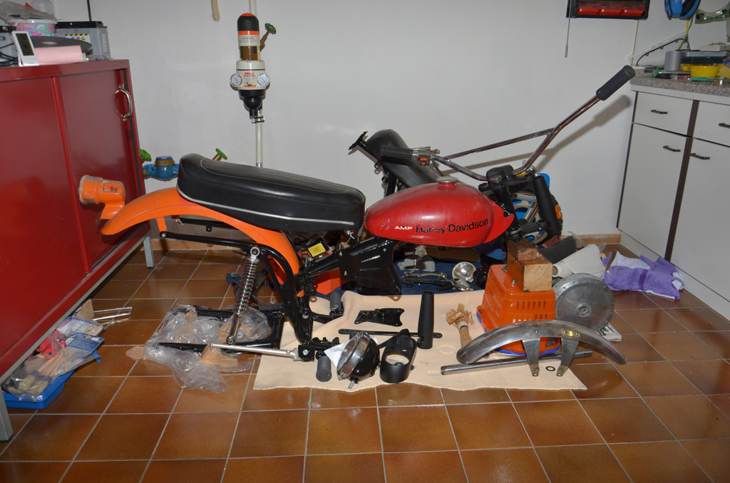
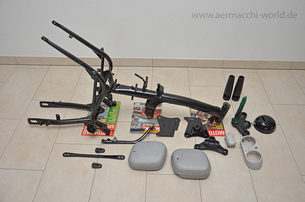
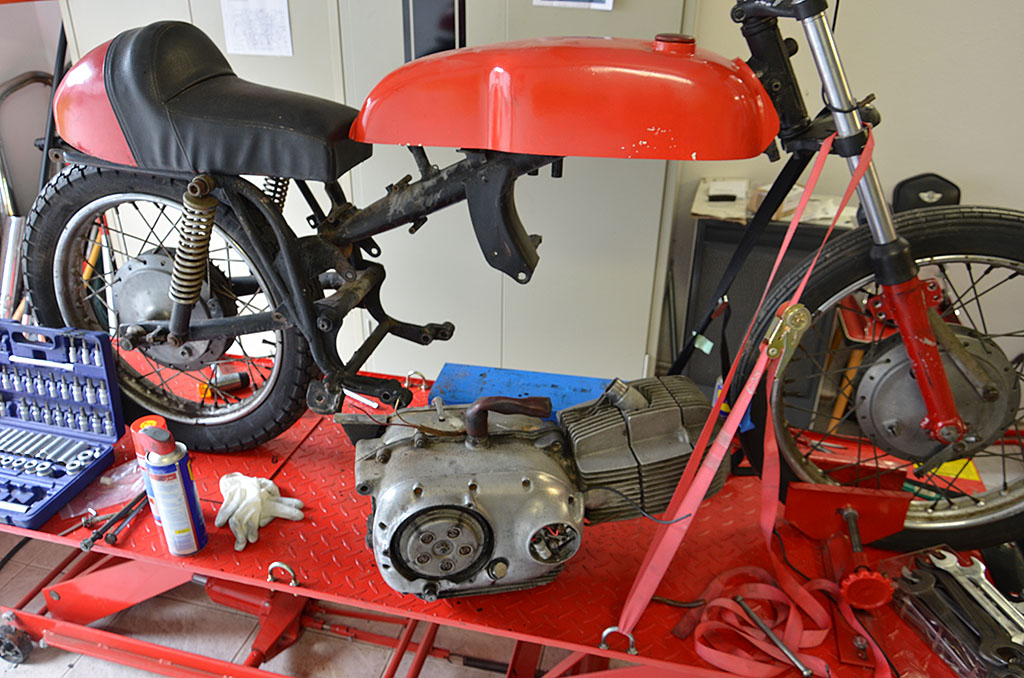
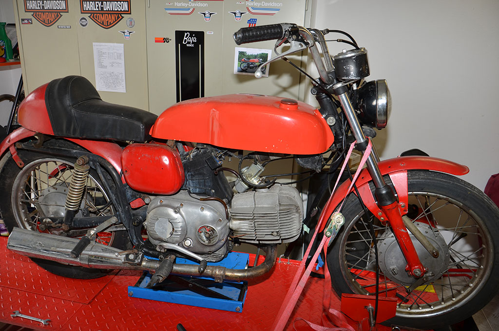
So, here we are. I have started disassembling the bike. I have got this small original Ala d’Oro gas tank and seat as decoration in my garage. I couldn’t resist the idea of building a café racer and so I tried how those parts might look. However, I will restore it back to original condition, but ONE DAY I might build a café racer!
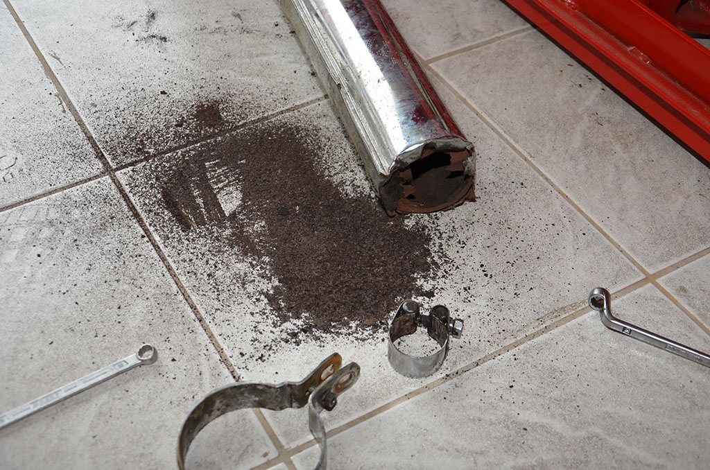
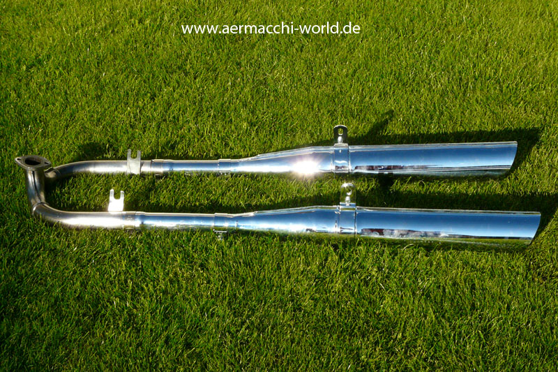
Oh yes, those silencers look pretty good. Just a little cleaning of the “Frankfurter Töpfe” and I can right use them again. 😉 Luckily I bought NOS replacements years ago and stored them safely in my basement.


I took some pictures before disassembling as construction plan for a later assembling. 😉


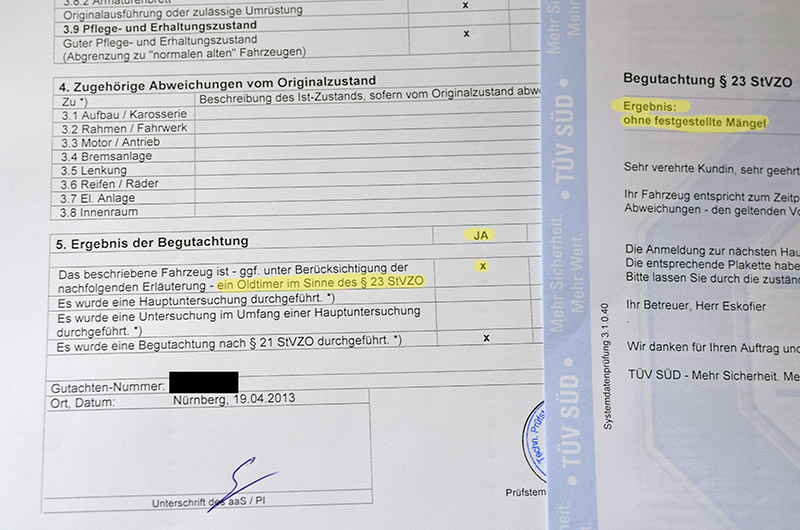
The first step for getting the bike road legal again. I bought the bike without any papers in 2006 and as it was imported in very bad shape from spain it never had any german papers. The officials tested it 2 hours for beeing safe, beeing within noise regulations and so on. I also had them investigating the bike if it is in original condition as it was sold by factory in 1974. a car or bike older than 30 year ins original and very good condition can be registrated as “oldtimer” in Germany which brings some benefits and safes taxes for example.
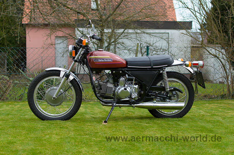
I did some pictures of the finished bike. I am very proud. It almost looks like brand new with very tiny cut backs. On one picture you can see my special bike trailer which can be lowered to ground and lifted with an air compressor for easy loading by one person only. I just had to modify it a bit as it is designed for bike bikes with wide wheel base like my HD FXDL. The trailer also has pneumatic shock absortion and I love it. If you don’t use the trailer it can be folded and easily stored in the garage!


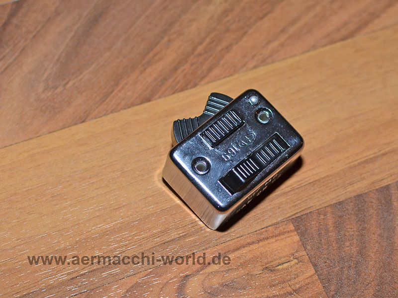
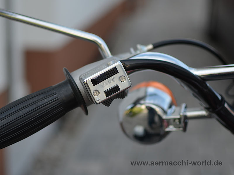
Finally I received the missing original handlebar switch for light, horn and turn-signals. There is no one in the world who can be worse at soldering than me, but in the end it is mounted to the handlebar and it works good. Thanks to Carl from the US for helping me out!
I couldn’t resist and I took this picture of my red Aermacchis on one of the first “not raining days” in this year after the longest winter ever!

I made a km/h scale and sticked it on top of the speedometer to make it road legal in Germany. 🙂
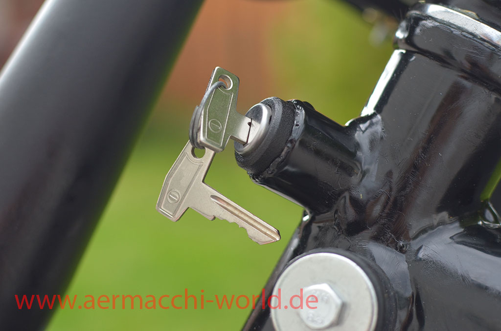
The local locksmith also made me a copy of the key for the ignition switch, as I had only one ignition key.
Video of first start after more than 6 years of restoration. The bike is already done. Not much to too anymore. Missing CEV169 and tach-drive.
I bought a new battery. 12V 19Ah as I started with the rewiring.

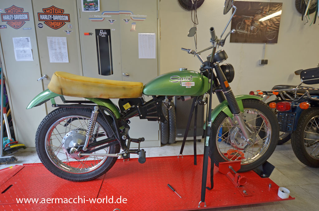
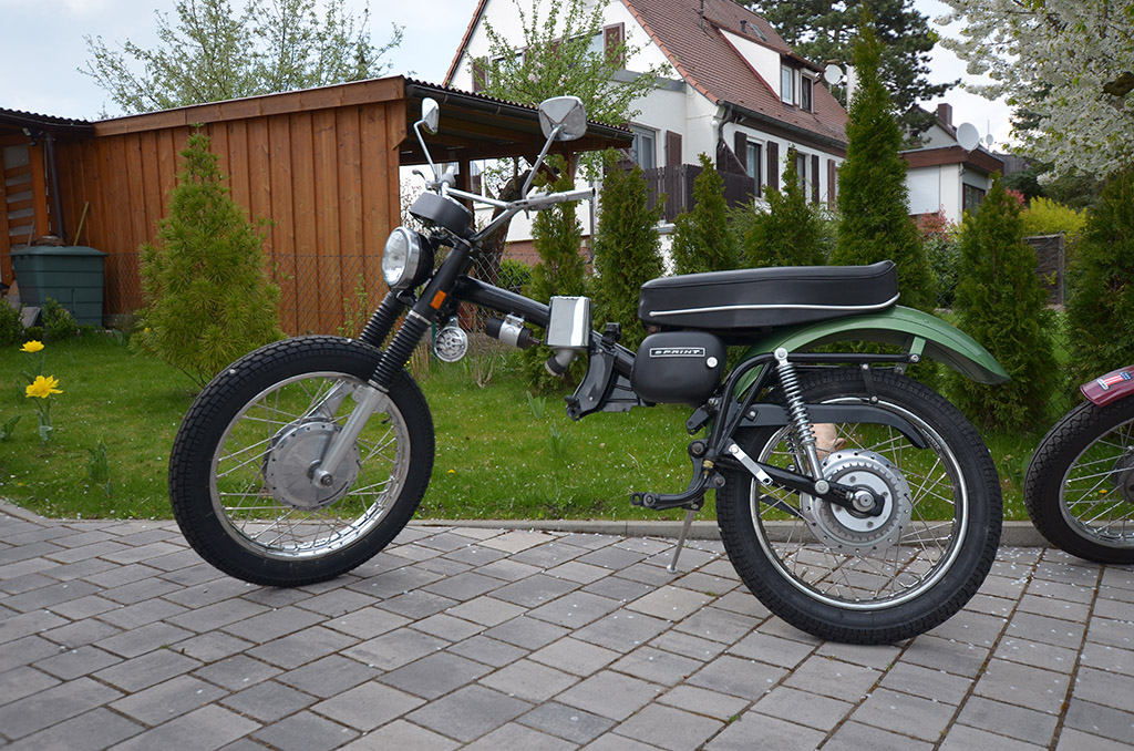
Here is a Picture of the bike how it Looks today. There is not so much work left, but the last two years I did not have any time for the bike. I will soon start on the bike again!
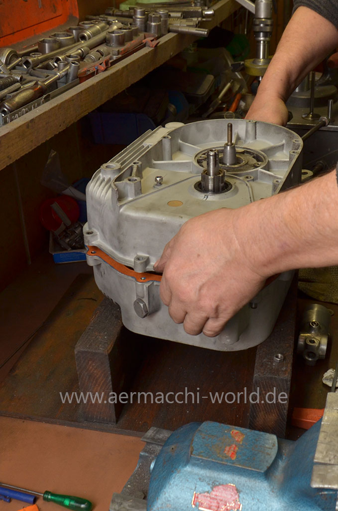
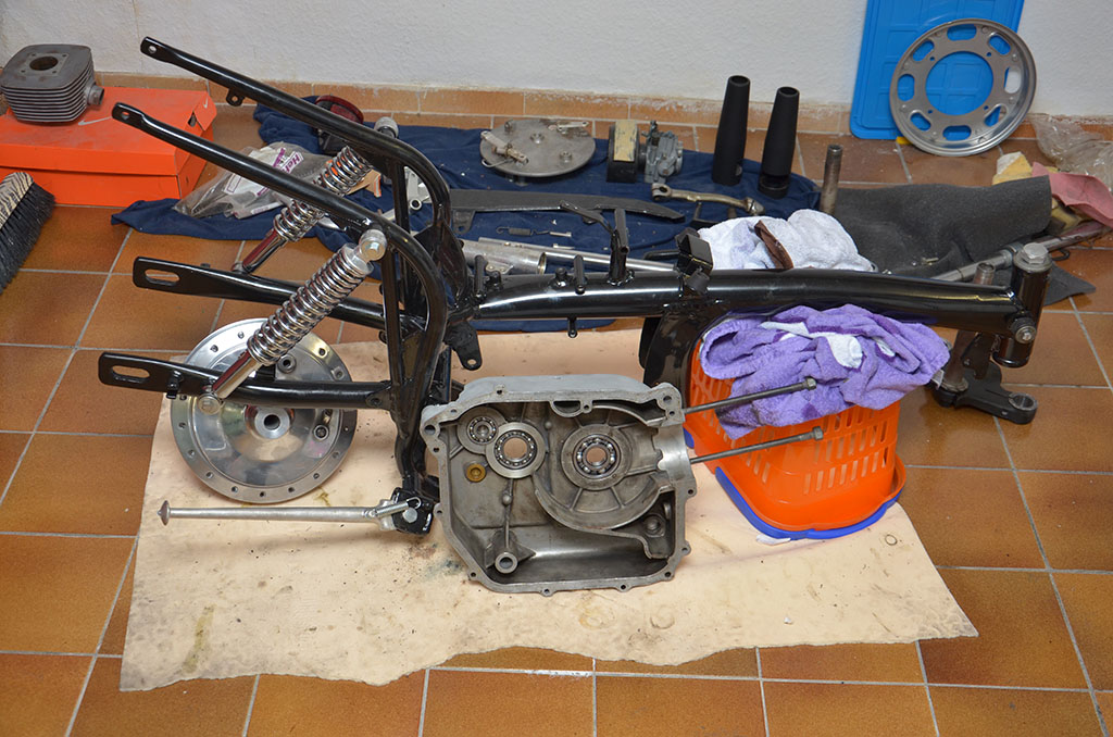
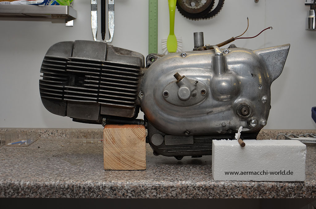
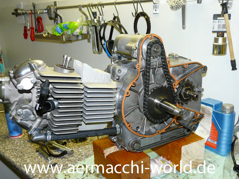
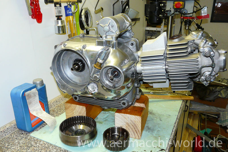
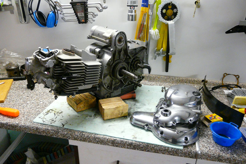
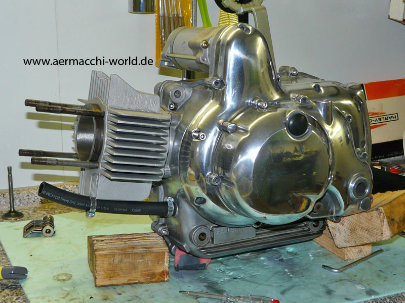
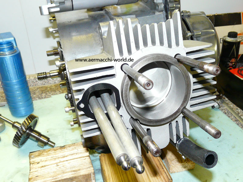
So, the engine is done. It is now back in the frame. 🙂
Ready to go back into frame!


Used original alloy trim stripes on the side of the seat. I had to trade them against something else and I bought new T-bolts to mount them. The seat turned out great, but overall it was an expensive fun to get it there.
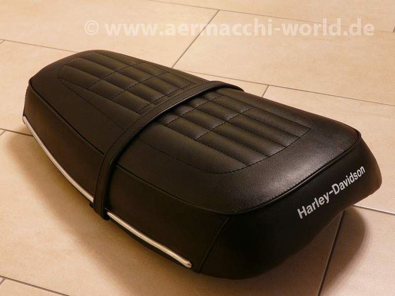
A saddler stitched the original pattern into the seat-cover and recovered the pan.


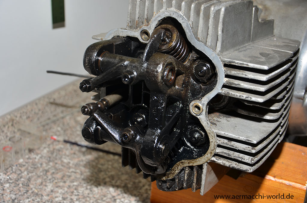
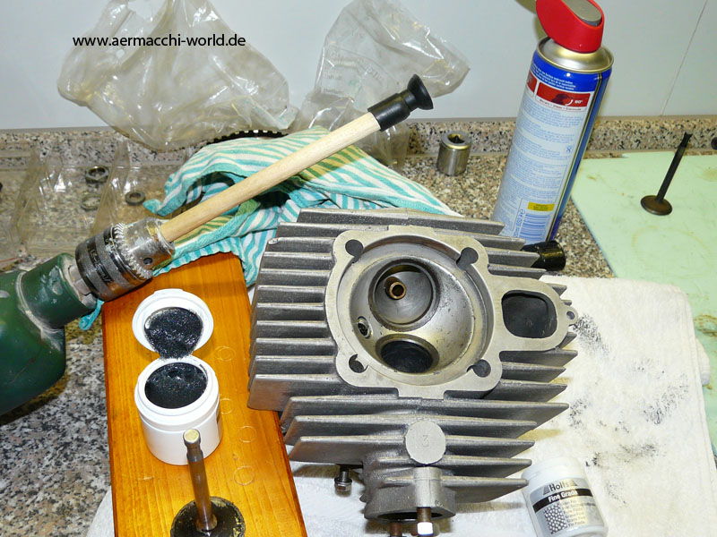
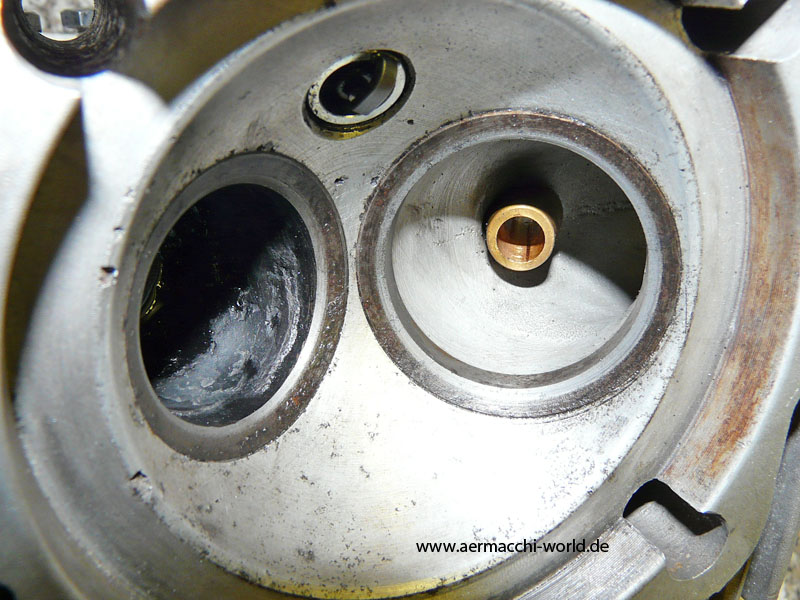
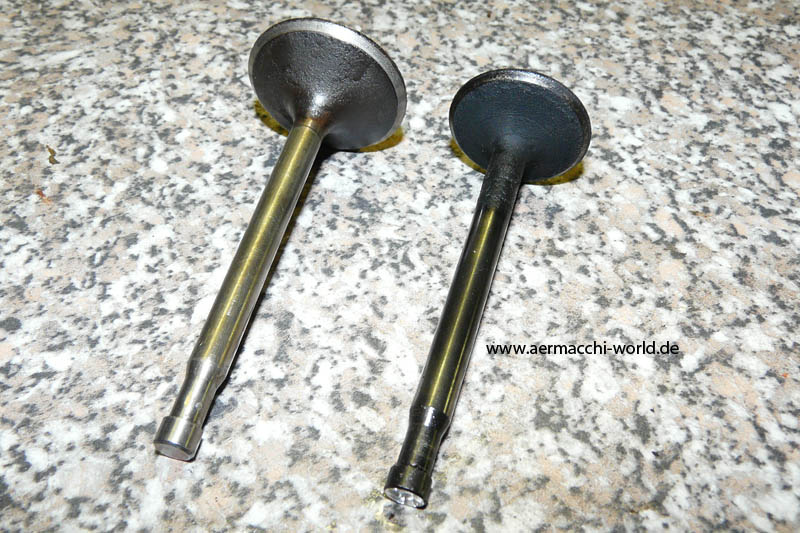
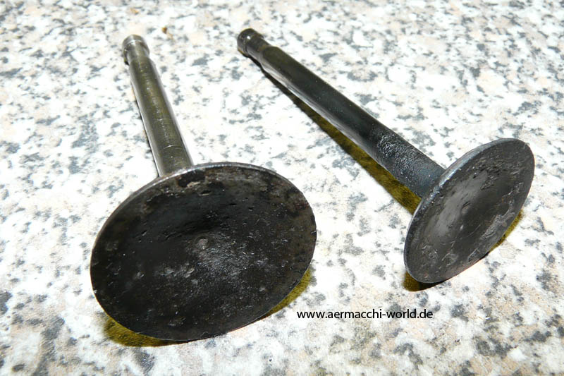
Cleaning the valve seatings
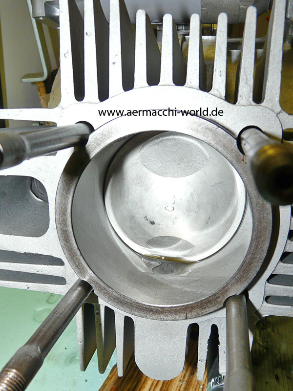
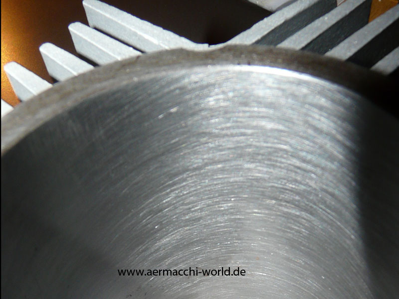
The sandblasted, rebored and honed cylinder is installed on the gearbox. The piston is a new 0.2 oversize together with new rings and new seals for the cylinder base.

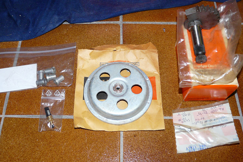
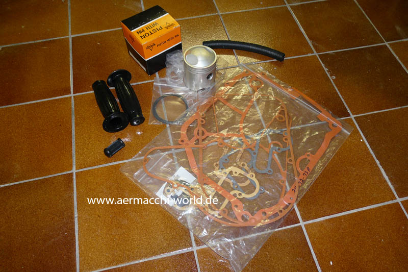
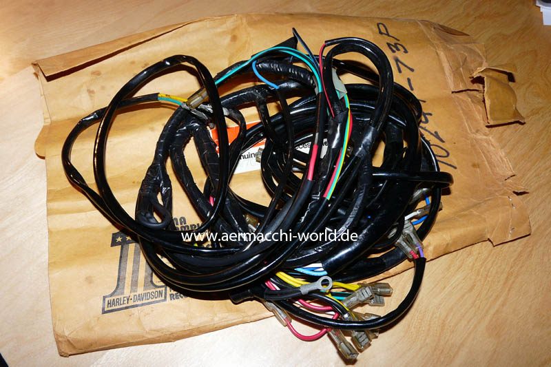
An oversize piston and rings, handlebar grips, a set of gaskets and a main wire harness
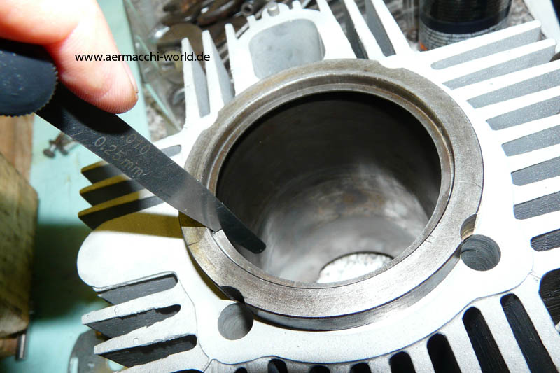
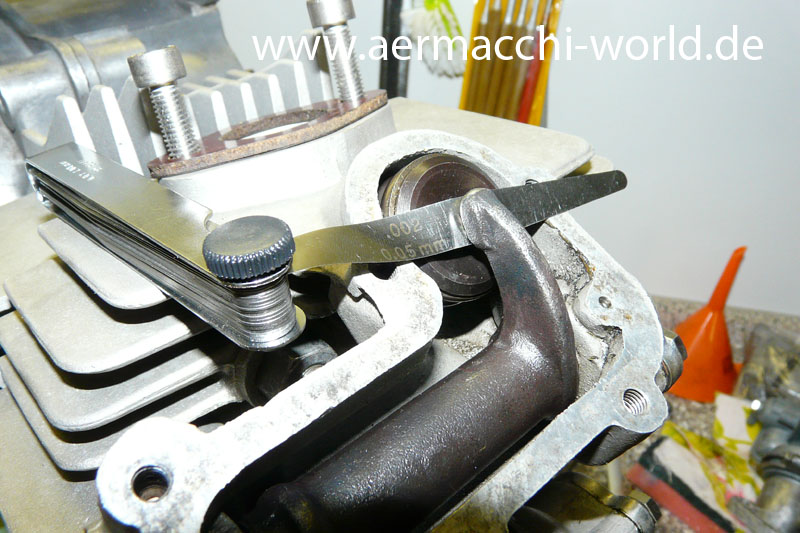
Both compression rings are within tolerance (0.10 to 0.16 in) but the oil control ring is of scale.


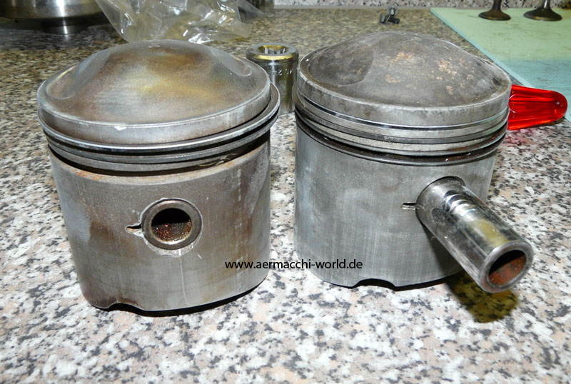
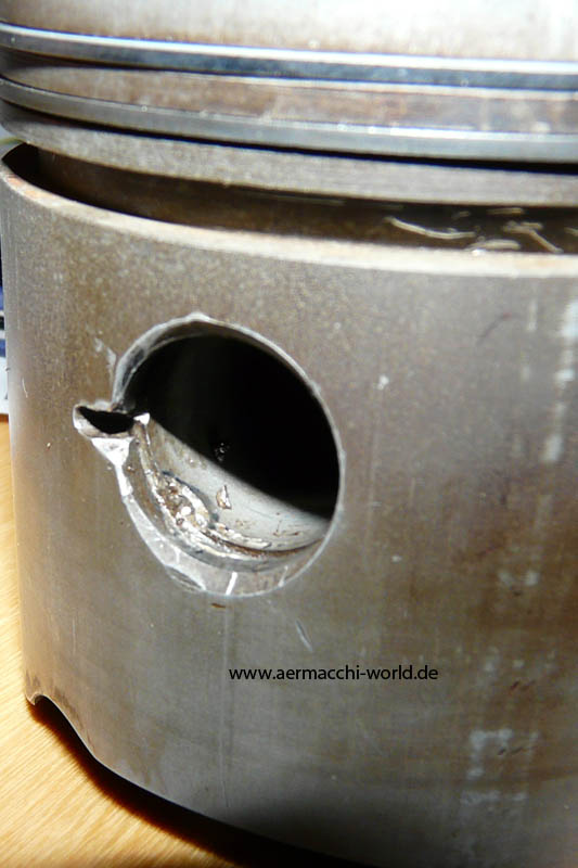
On the left side you can see the piston that came with my replacement cylinder. It looks good on the first look, but if you look closer there is no doubt a butcher worked on it. Now I have a usable replacement cylinder but no piston for it.
The used replacement cylinder I bought on ebay. Got it back from bead blasting today. On the second picture you can see parts I am going to send out for polishing and chroming.

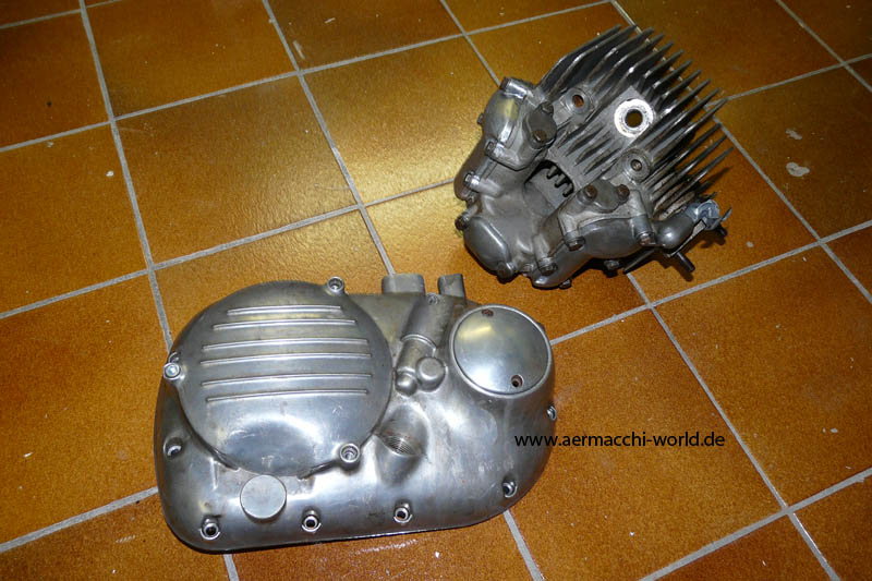
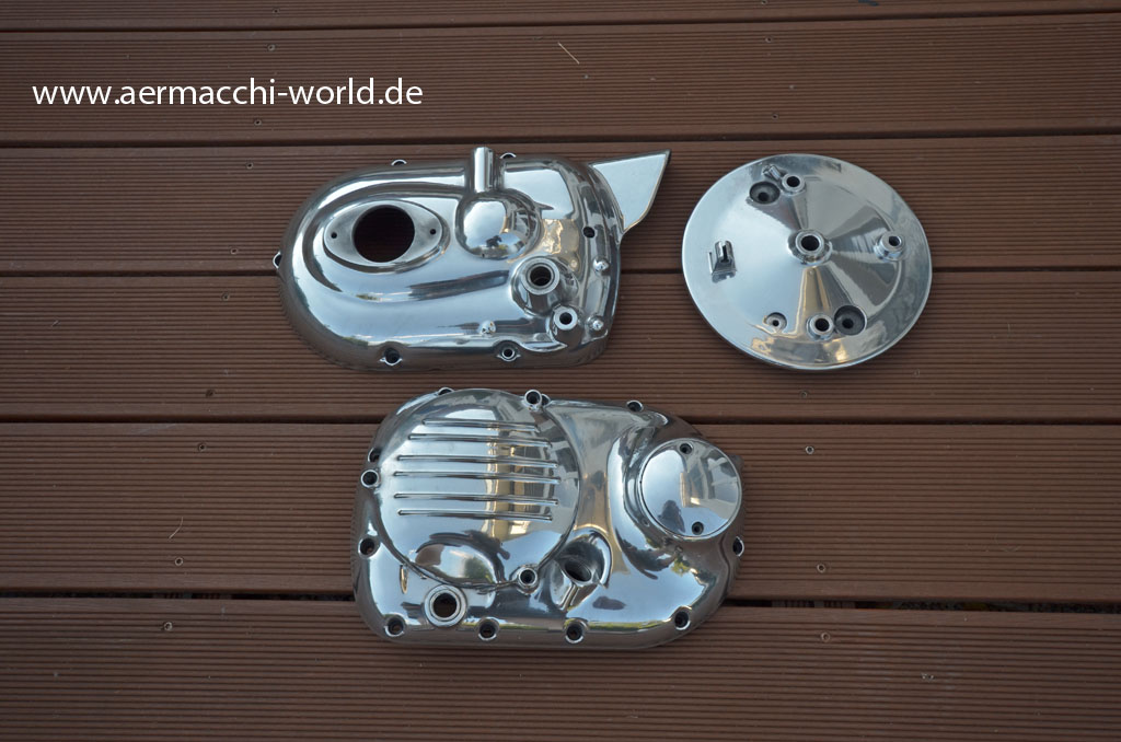
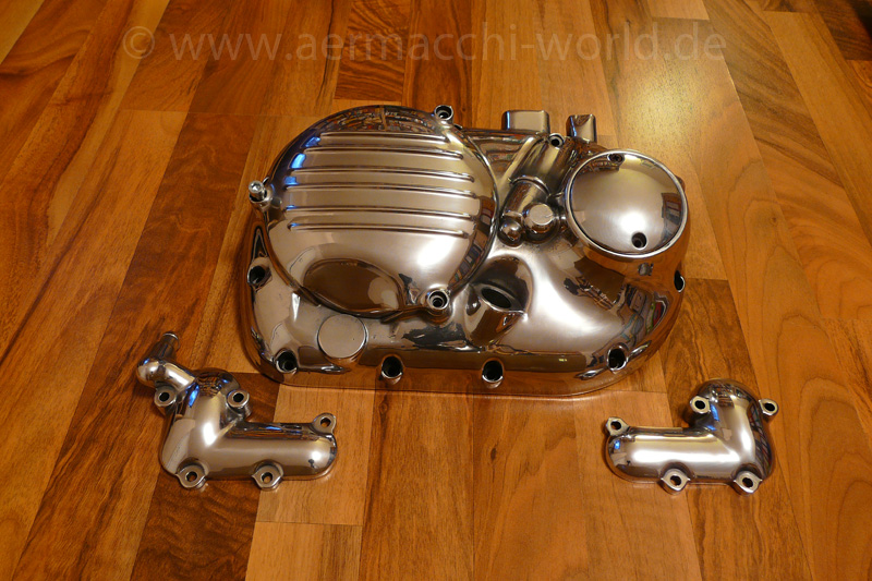
Handlebar rechromed and right side engine covers polished to shine.


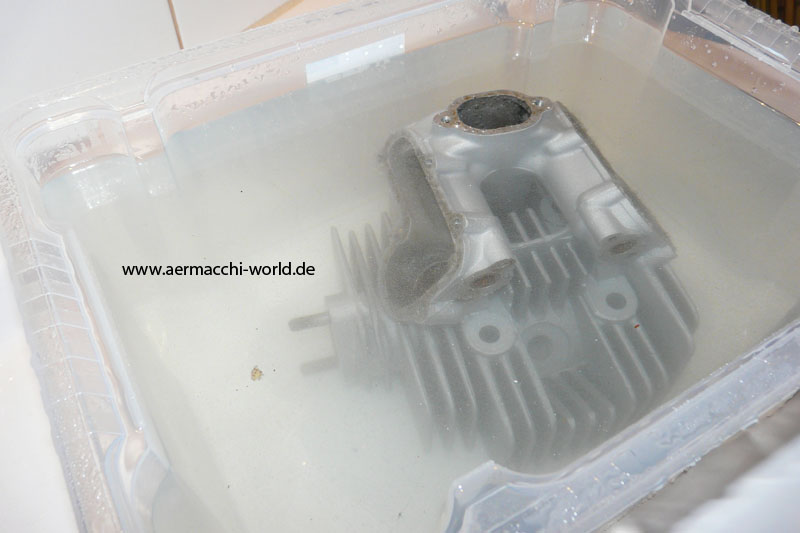
There was so much sand in the cylinder head from sand blasting, I had to bath it several times to get it clean again.

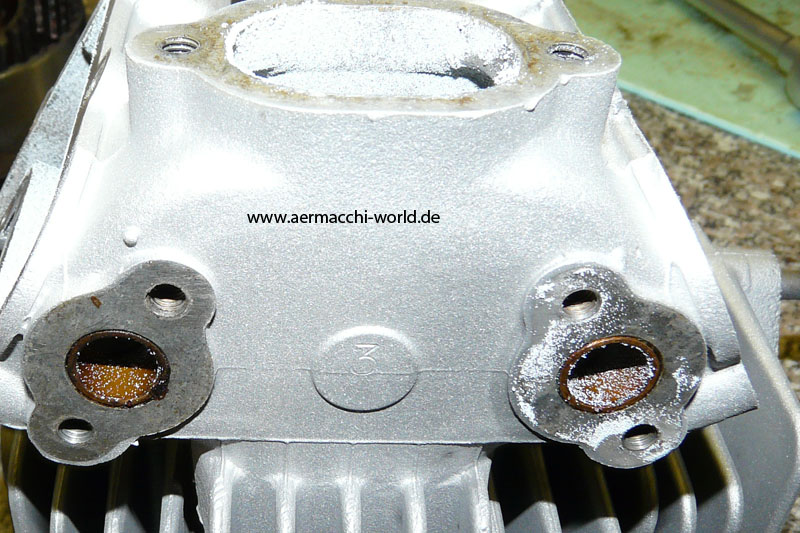

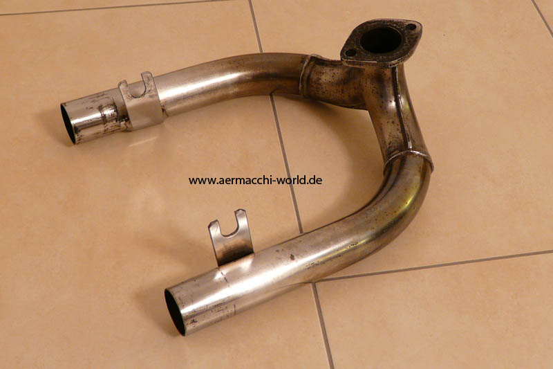
Here you can see the sand blasted cylinder head and the very nice Y-Pipe which I got from Dave.

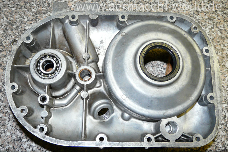
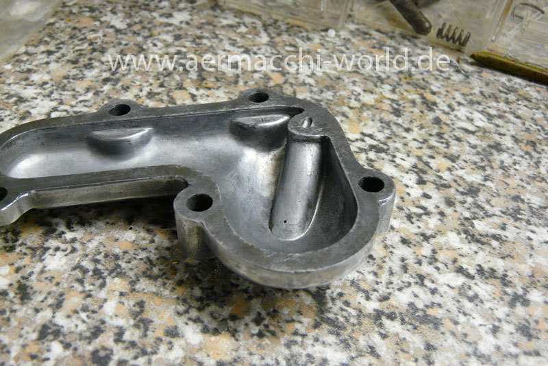
Right side cover

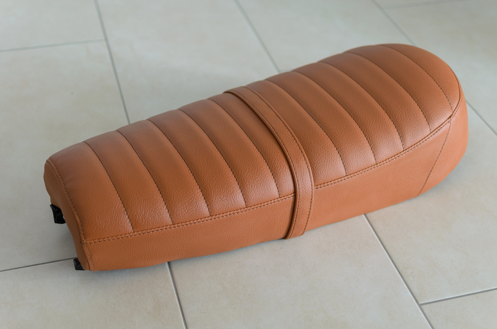
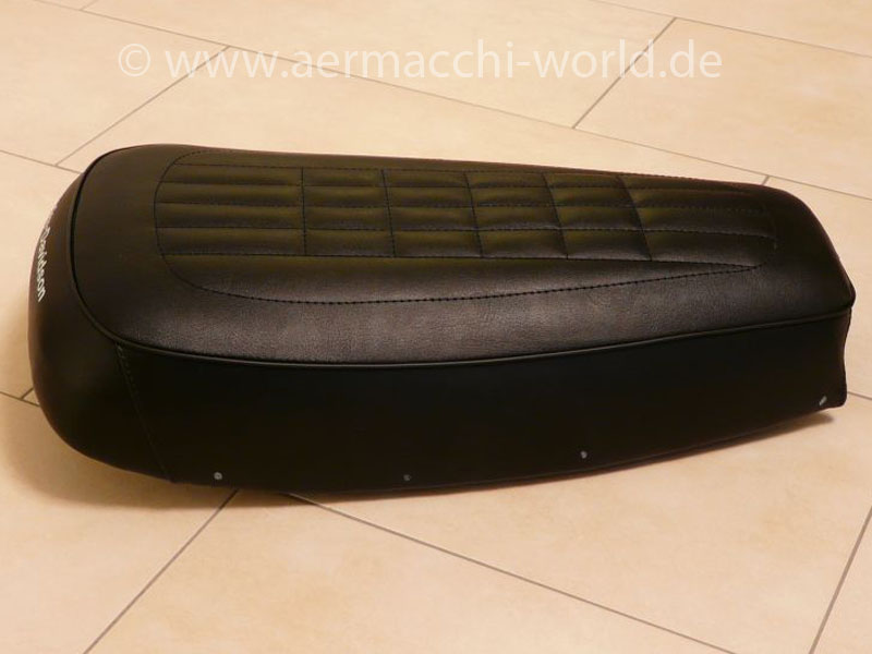
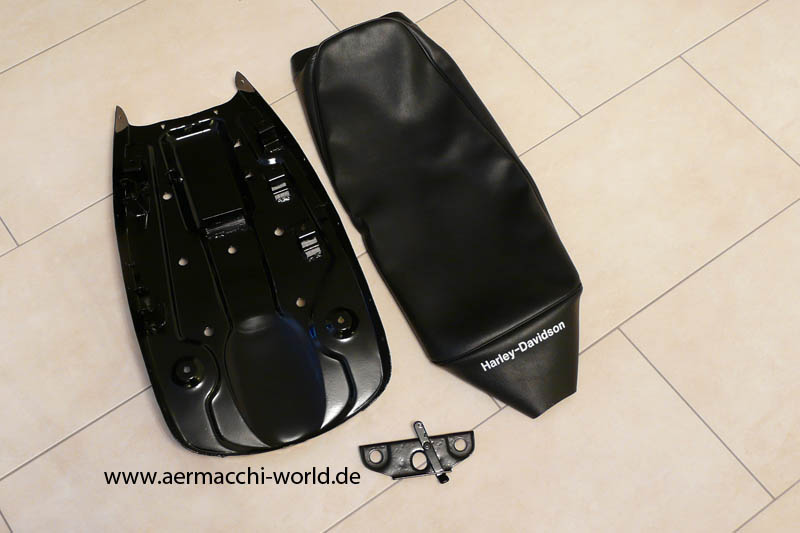
Here you can see the freshly powder coated seat pan and the reproduction seat cover I bought. The seat cover is professional made but does not have the original pattern on top.
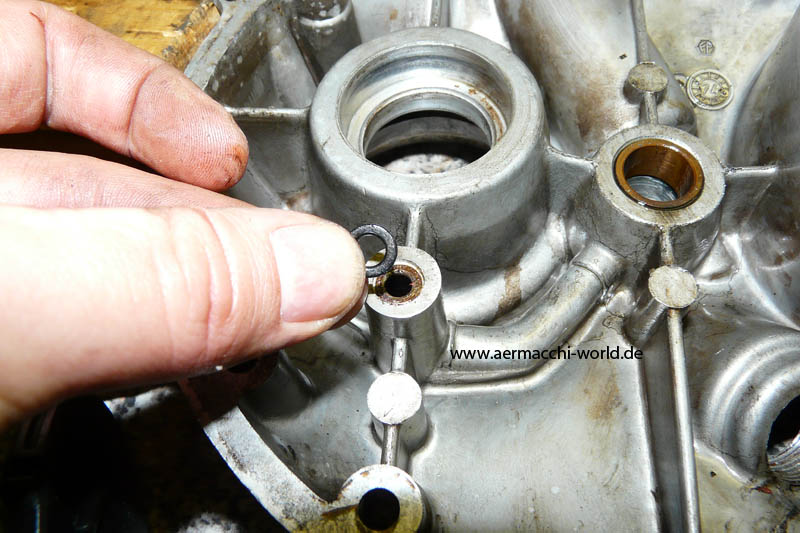
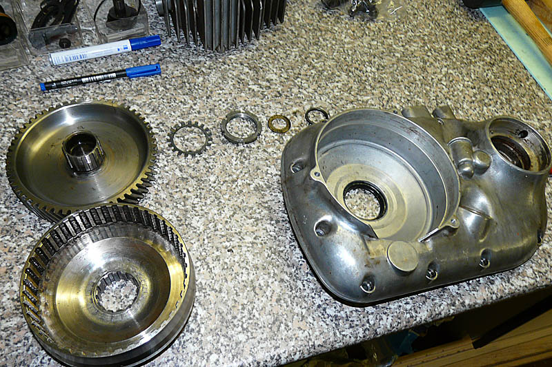
I have removed all parts from the right side engine cover so I can send it out for polishing. The cylinder head need cleaning as well. The oil seal for the clutch basket is a42x56x7 the ball bearing for the advance is a 6203 and the oil seal a uncommon size of 17x32x5.

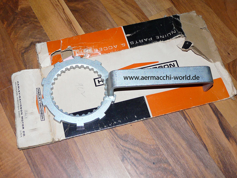
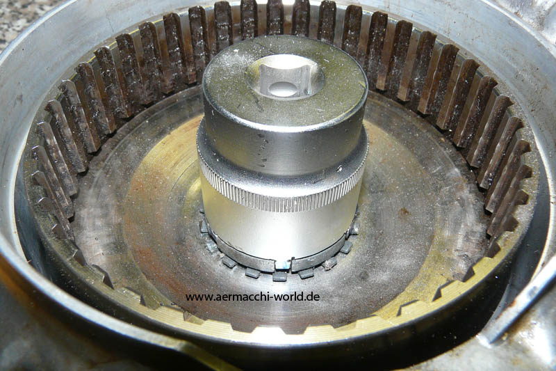
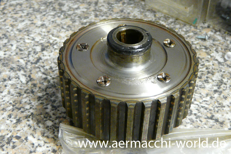
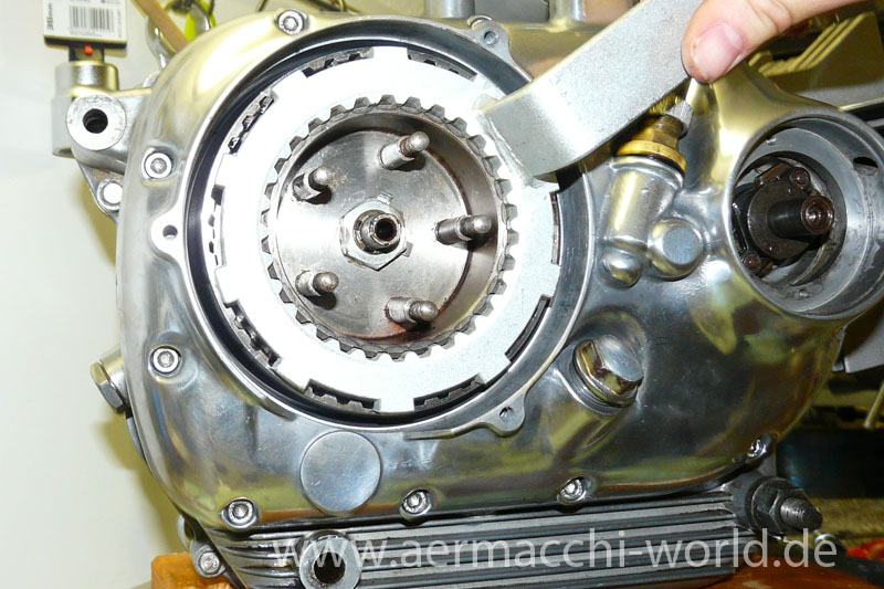
High precision, fine german engineering for a special tool 😉 to open the inner clutch hub nut.
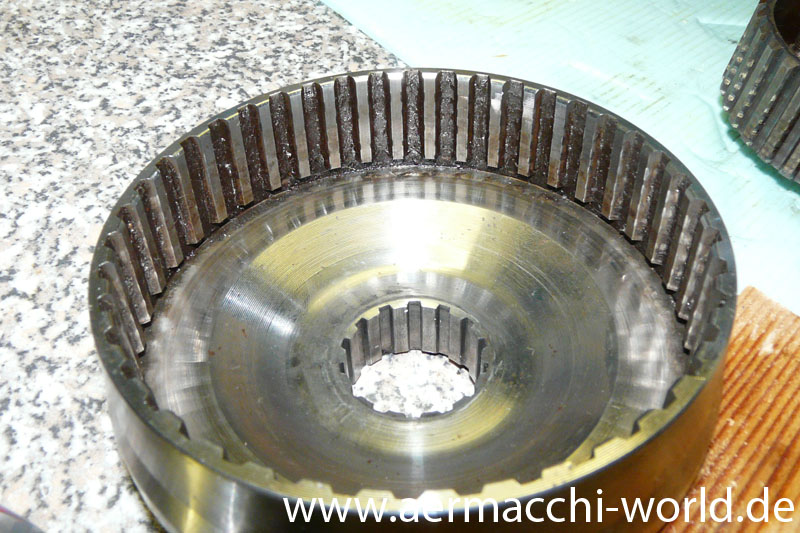
By the way as I have a 74 SS-350 this is the improved alloy clutch hub which was introduced on late 73 models. It can be identified by the higher number of toothes compared to the earlier steel hub. The late version also needs different clutch plates.


