Dashboard

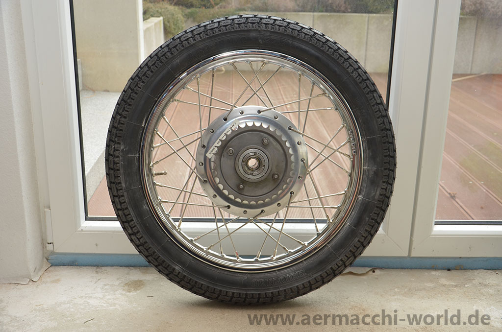
Rear wheel redone
Guide to arrange drive gears
Before you start:
There is no guarantee for the correctness of the information provided. That following steps describe the procedure for my 1970 GT-350. It’s a different procedure on other model years!
To my knowledge (again, without guarantee) this is valid for 1969 to 1972 Sprint 350cc street bikes and not for earlier bikes and not for the 1973-1974 electric start!
Please ailways use a few drops of oil to fit the parts together.
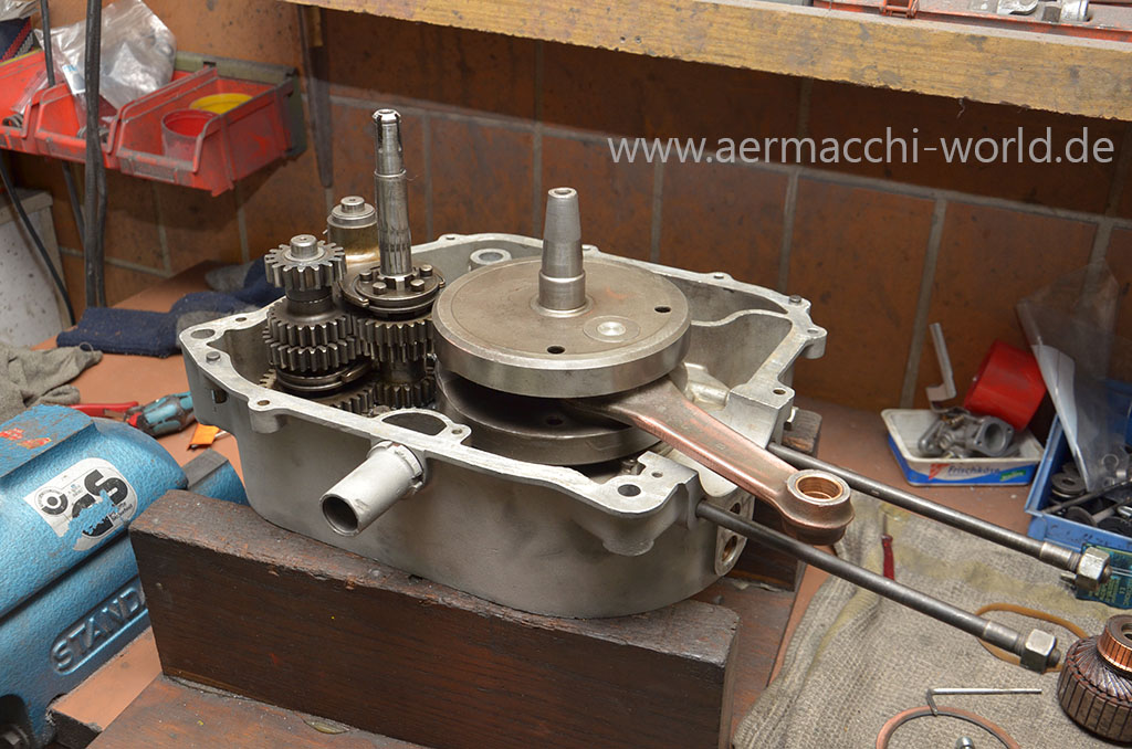
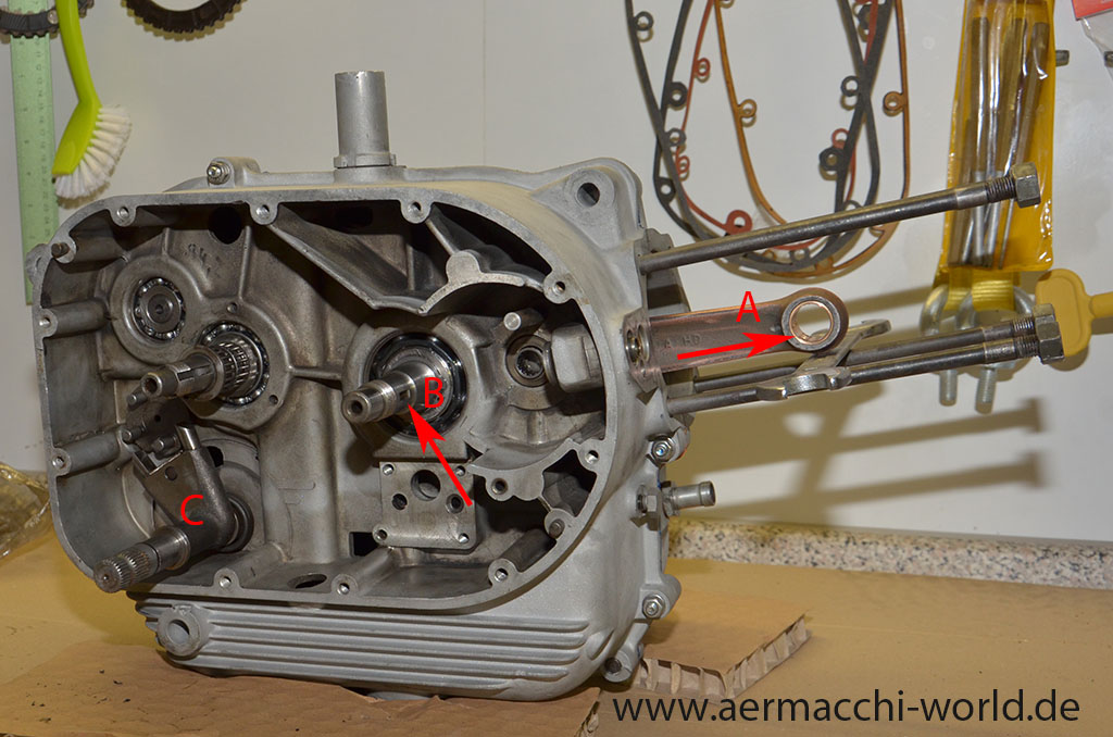 Pic 1.
- We start with an empty right side crankcase. Only the shifter pawl carrier (C) is already put in, as it must be inserted before the primary drive gear.
- Pull out the connecting rod (A) to tdc (top dead center), this will move one of the three notches (B) on the flywheel shaft to 3 O’clock position.
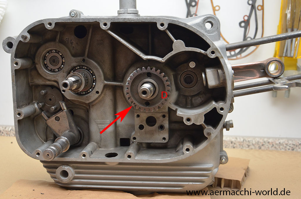 Pic 2.
- Slide clutch drive gear (D) on shaft of flywheel. It will stop in the correct position because of the conus of the shaft. Don’t turn the shaft! The mark on the clutch drive gear (arrow) is of no meaning at this point.
 Pic 3.
- Put the woodruf key (E) into notch of the shaft. It must be the notch at 3 O’clock positon while connecting rod is at tdc position!
 Pic 4.
- Slide pinion gear (F) on shaft with woodruf key in position at 3 O’clock and make sure the mark on the pinion gear points to 3 O’clock also (arrow)! It sits correctly if the surface of the pinion gear touches the surface of the clutch drive gear.
- Put the lock ring and nut on the shaft. One latch will be bend into the notch of the pinion gear the other around the flat side of the nut after the nut is tightend! (These steps are not pictured)
- When tightening the nut you must make sure the shaft will not turn.
 Pic 5.
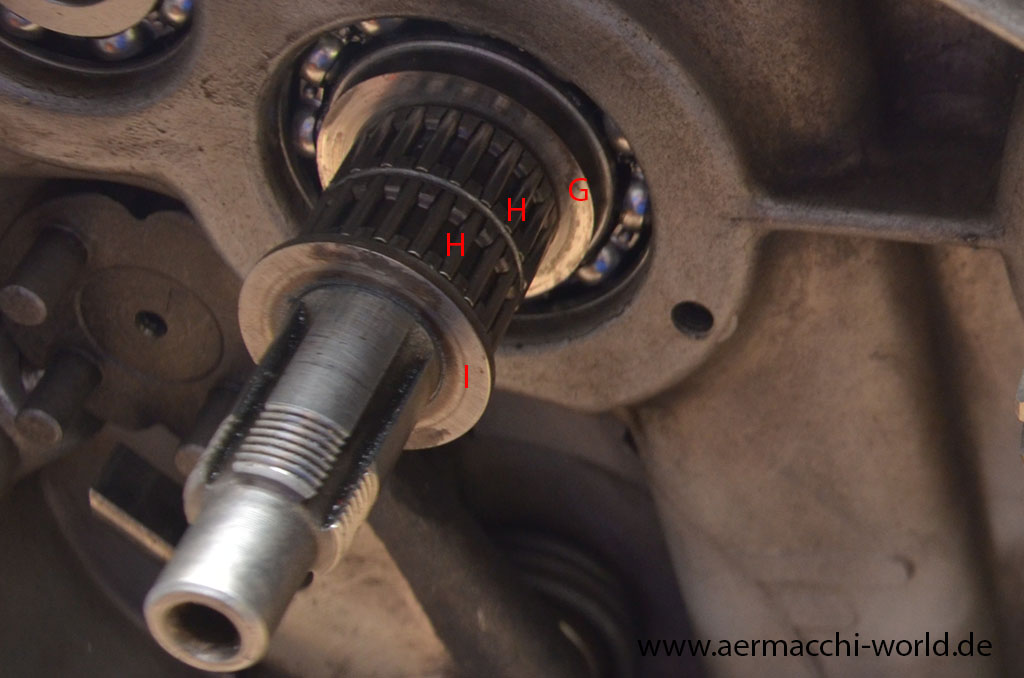
- Next we put the primary drive gear on the transmission shaft. On that picture you can see what parts must be fitted inside the gear. A thick spacer (G) that must have the correct thickness to arrange the primary gear in one line with the clutch drive gear (D).
- Inside the gear are two roller bearings. On top of the bearings will fit another distant spacer.
 Pic 6.
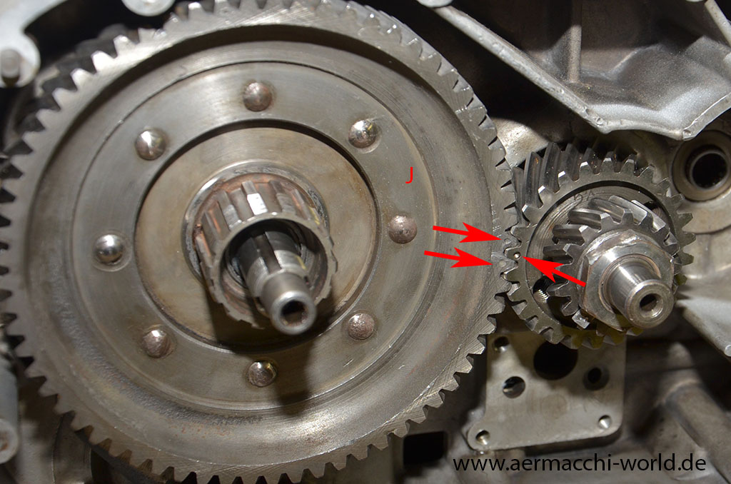
- Put the primary drive gear (J) on transmission shaft and don’t forget the stuff explained in Pic 5. You will need probably 2-3 trys to make the two marks fit the one mark of the clutch drive gear. For that operation you may turn the flywheel shaft with the clutch drive gear.
- The marks on the primary drive gear (J) and the clutch drive gear (D) however are not time critical. It’s just the way the teeth are fitted together by factory. That’s the reason for using gears always in matched sets! If you don’t, you will risk damage to gears.
 Pic 7.
- Next we put the roller bearing (L) for the camshaft into crankcase and also set the two tappet guides in (K).
 Pic 8.
- A spacer will be used on camshaft to allign the camshaft gear exactly to the pinion gear.
- I will not describe how to fit the camshaft gear to the camshaft as it can only be fitted in one direction
 Pic 9.
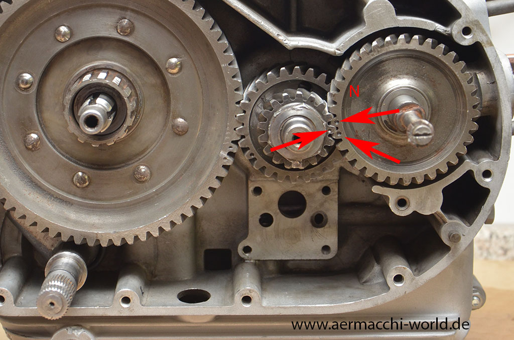
- Put the camshaft with gear (N) into the roller bearing (Pic 7.) and arrange the two marks with the one mark on the pinion gear (F).
 Pic 10.
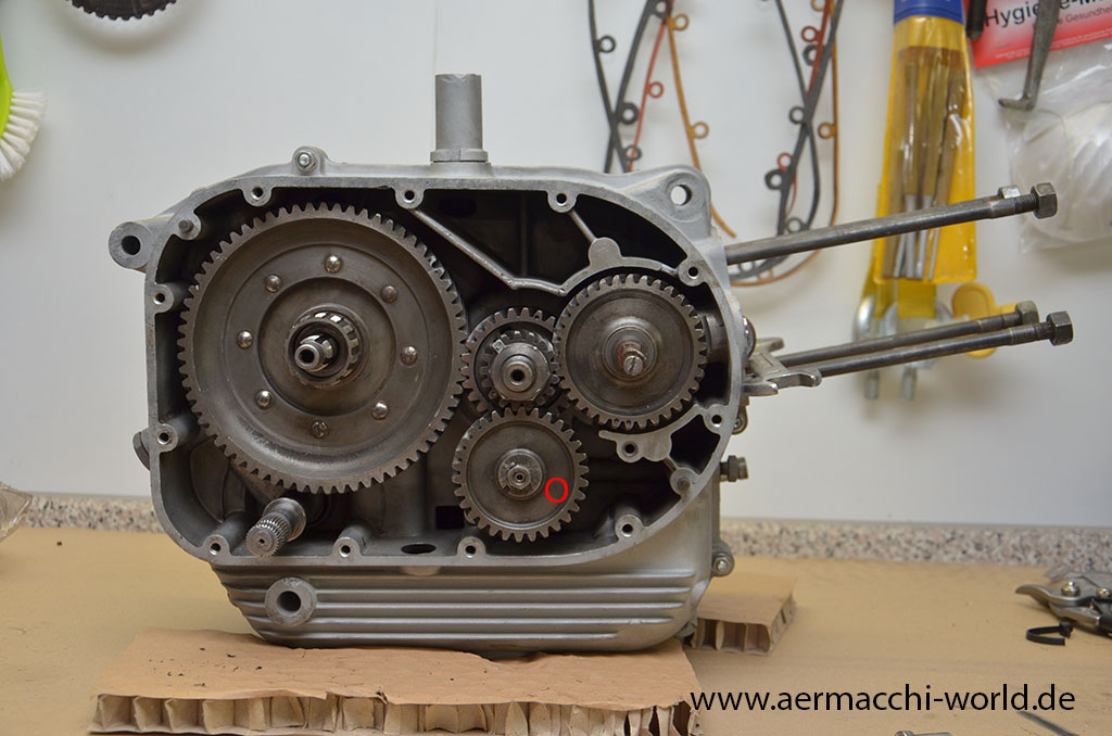
- Screw the oil pump into case (4 screws) and make sure the O-Ring is still on the oil pump for a sealing to the crankcase. Put the gear on the oil pump shaft. It is not time critical and has no mark so it doesn’t matter how it will fit together with the pinion gear.
Back together
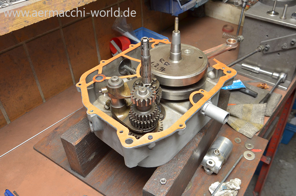
Everything within factory specs now and putting engine cases back together.
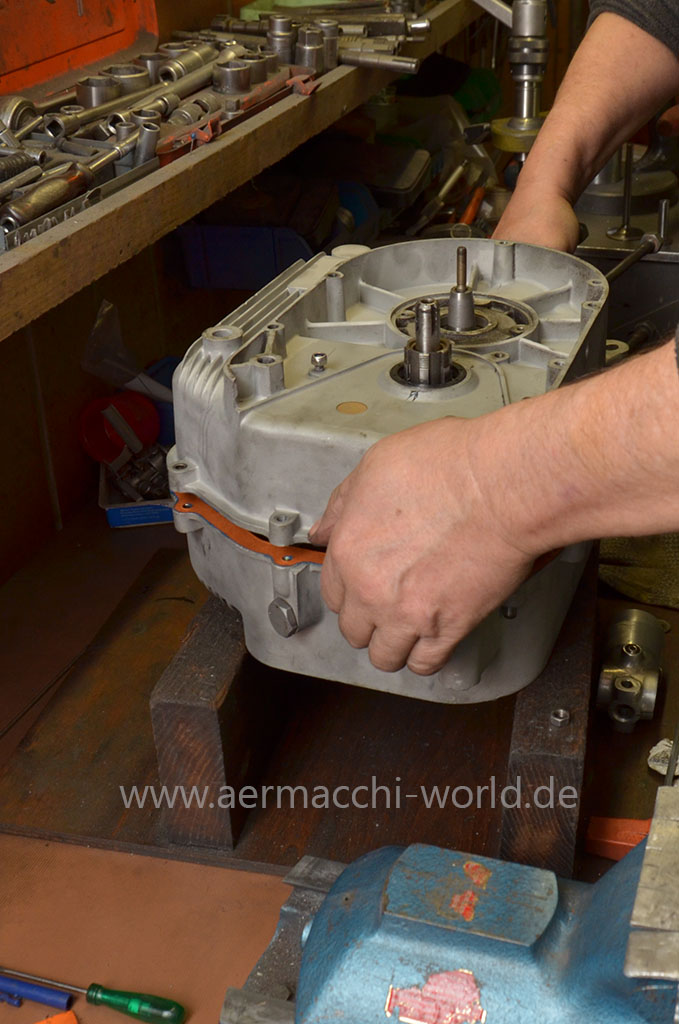
Putting together


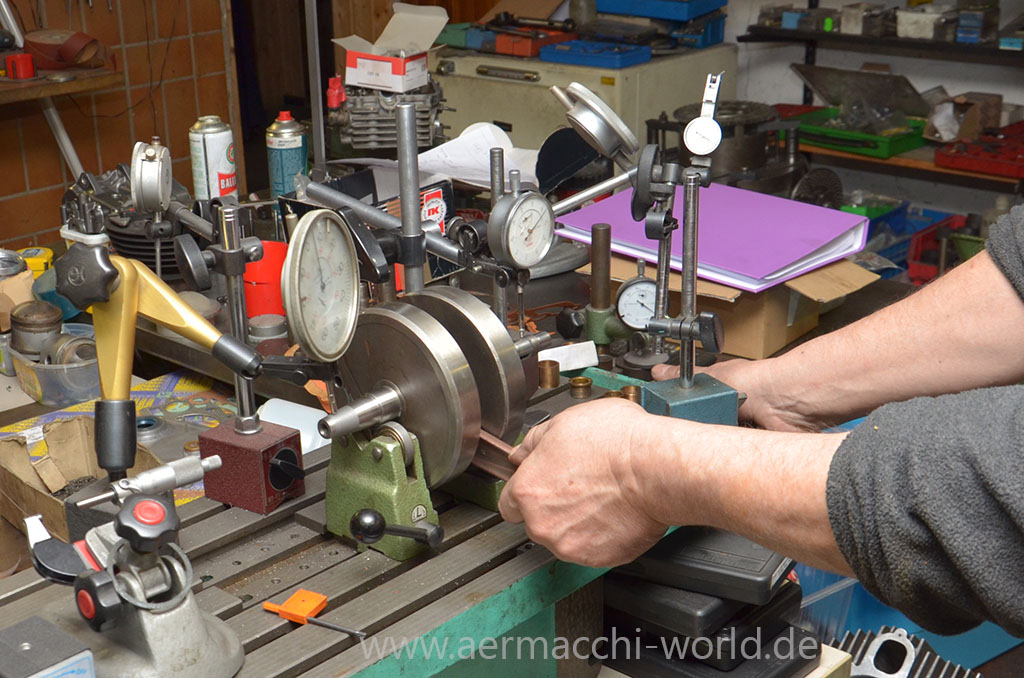
The new ballerings, the new rod and the overdone flywheel getting back together. Rudolf than trued the flywheel to 0,01 mm which is much better than factory Defaults.
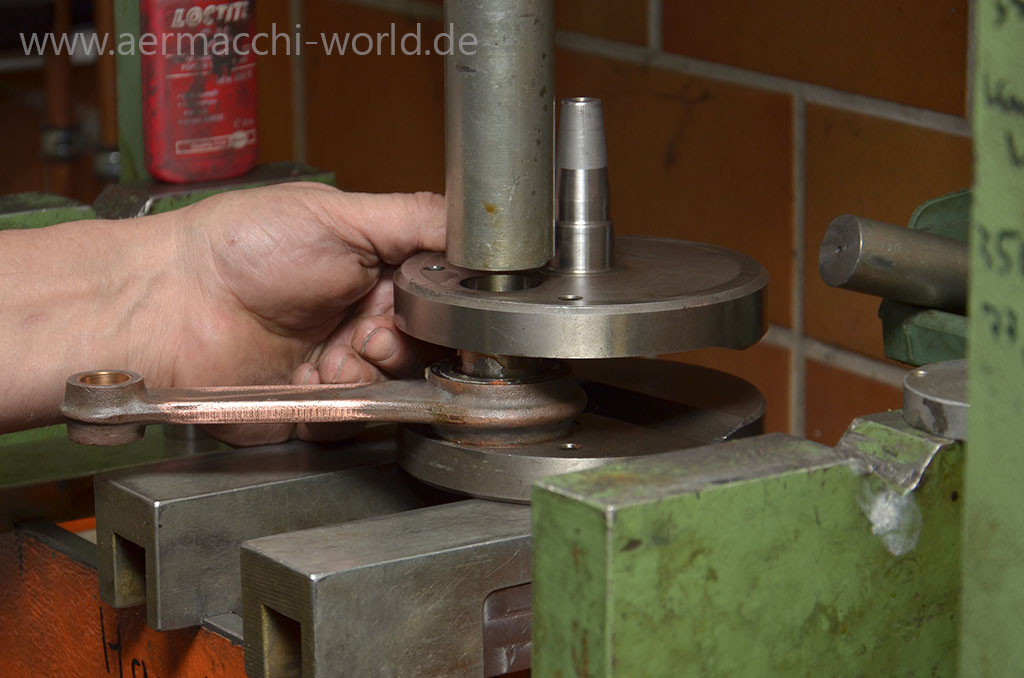
Crank pin
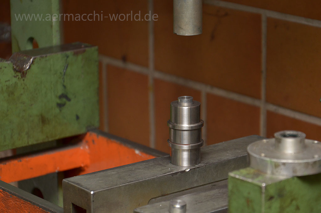
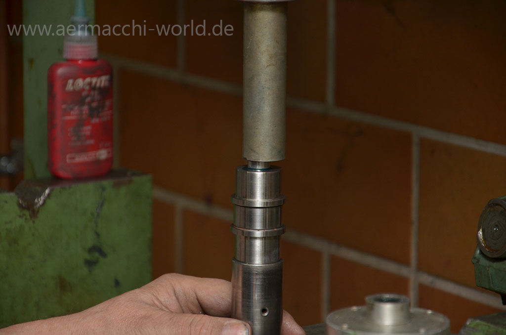
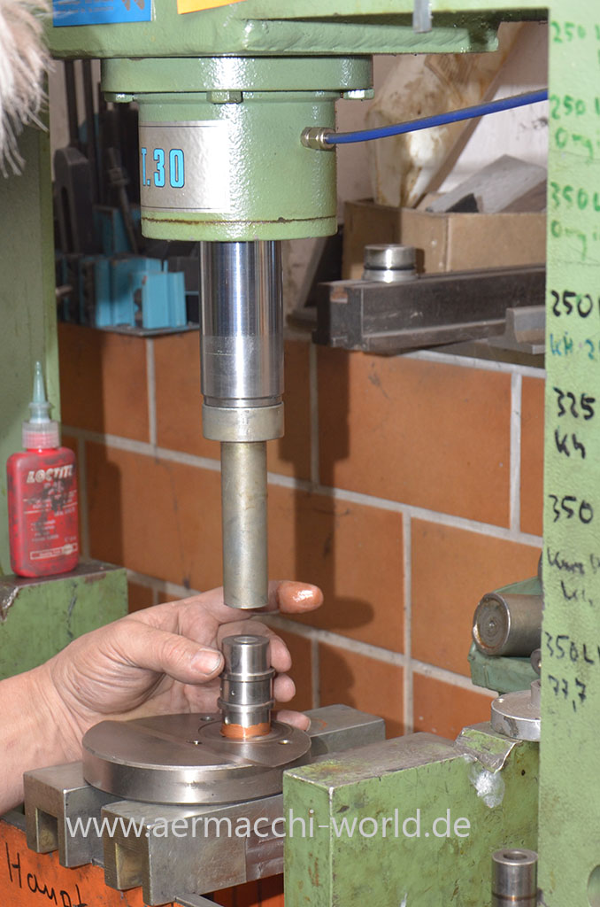
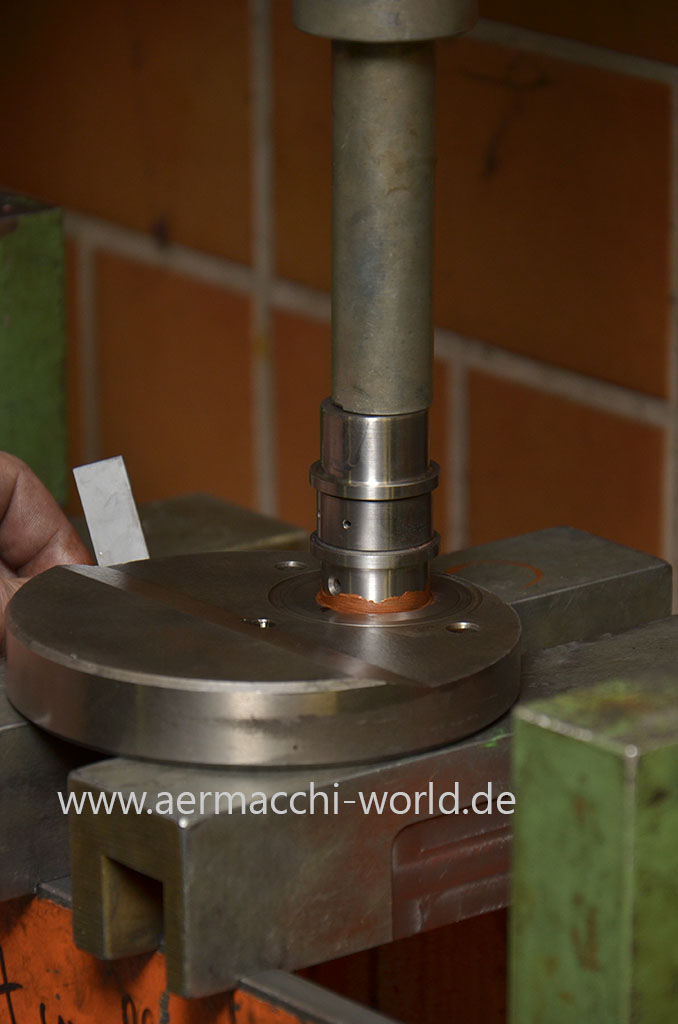
Pressing new plugs into the crankpin and than pressing the crankpin into the flywheel with copper paste. You need about 5 tons of pressure for this.
NOS connecting rod


We polished the crankpin so the new bearings do not have to cut off material. The original bearings which consists of two parts rollers in each cage we replaced with “one-part only” bearings as you can see on a later picture.